If a Blueprint calls for ASME Y14.5 wouldn't this be the standard rules apply. How would I know if and when to apply ISO? I have yet to see anything on a blueprint stating this. The reason I bring this up is for the good old Profile callout. Before I make an argument, I want to cover all my resources. Customer already claims in an email that PC-DMIS is not capable of doing this. I and everyone on here already that's horse_S_H_I_T. But its Friday and I'm ready to P_I_S_S someone off
again I can't thank you and everyones input. Like Vinni mention in an earlier post, basically bite the bullet and just report it. The problem is, this same customer time and time again, continues to have bad call outs, changing the rules. As they go along. Its not the matter of I get paid by the hour. Think of it this way, Say you make an oil painting, and I come along and say, the water shouldn't be blue, make it green because there's algae in there. The leaves on the tree, you painted them green, I'm thinking its autumn, so go ahead and make those leaves brown. All of a sudden that picture isn't looking so good. And you and I both know, not all the time, but sometimes, SOMETIMES, you start making changes to your program. Things start to act a little goofy, and your program (oil painting) isn't looking to good anymore.
Make them sign off on it. Generate a document that says they understand that their print specifies ASME and they want it reported ISO and make them sign it. He said, she said, is not good enough if something bad happens and you have to answer for it.
I have been taught for many years that the correct ASME way to report profile is to double the worst reading (for bi-lateral) profile tolerance. Its a matter of reporting the results in the same context as the tolerance. For instance, position for a hole location has a diametrical tolerance. But you calculate the radial deviation (hypotenuse) THEN multiply by 2 so that it is reported
in the context of the diametrical tolerance. Similarly, bi-lateral profile is toleranced as a WIDTH (like positions diameter), but you find the greatest deviation on a side (like positions hypotenuse) THEN multiply by 2
so that it is reported in the context of the WIDTH tolerance.
This video explains it well:
https://www.youtube.com/watch?v=lWvYH8wn5Ac ... if that link doesn't work go to youtube and search for "GD&T Tip - Reporting Profile" by Tec-Ease.
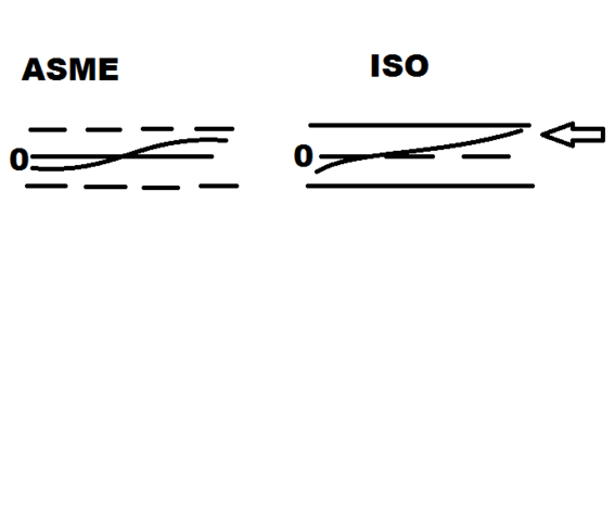
Kevo_cmm , That would be wrong. Lets see if I can simplify this. First I have both the ISO 1101 Book and the ASME book 2009 and 1994 and actually 1982, which back then was ANSI and not ASME. The ASME is considered a Condition, ISO is a boundary(X2) Each one looks at profile very differently. ASME starts from middle takes highest reading and lowest reading, if one is a negative number and the other is a positive, you add them together and that is your total CONDITION. With ISO its fairly simple your starting from the outside going into 0, Both sides move equally together, where the X2 comes in. until you hit your highest point or your lowest point, and your profile lies within that boundary.
Well, that's not entirely true either Kirby. ASME doesn't say to do it either way (or not to do it which way). Y14.5 doesn't dictate how to report profile (or anything else). So, there's no way to say that one way is "the wrong way".
VinniUSMC Yes, I agree that the standard does not specifically tell you how to report the bi-lateral profile deviation,
and
KIRBSTER269, what you wrote does make sense, from a certain point of view. As Vinni points out your understanding is also not specified as THE way to report it.
Consider this:
Does the standard specifically tell us how to report position deviation either? Does it say to calculate the radial deviation and multiply it by two?
I just spent ~30 minutes using search terms like multiply, hyp, calculate, circular, radial, two, diametral and did a visual scan of the true position sections of the 94 standard, and did not find anything that tells us how to calculate and report the positional deviation of a hole location. (You might be able to argue that the standard
implies how it should be reported.)
Yet everyone knows that we do it by : =(SQRT(A^2+B^2))*2 (to state it as an excel formula).
Why do we report it that way? Because we know that we are dealing with a cylindrical tolerance zone and that if we dont double it, we would be reporting it as if it were a radial tolerance zone.
(Note, I was first exposed to true position at a military manufacturer 35 years ago who actually used Radial true position on their prints. I haven't seen anyone else use it since then).
Likewise, it makes sense that with a bi-lateral tolerance zone whose width is centered on a plane or line, you would relate the greatest deviation (which is either on one side or the other) back to its width tolerance zone by doubling it.
I agree with Don day of Tec-Ease. Doubling it only makes sense.
VinniUSMC Yes, I agree that the standard does not specifically tell you how to report the bi-lateral profile deviation, and KIRBSTER269, what you wrote does make sense, from a certain point of view. As Vinni points out your understanding is also not specified as THE way to report it. Consider this: Does the standard specifically tell us how to report position deviation either? Does it say to calculate the radial deviation and multiply it by two? I just spent ~30 minutes using search terms like multiply, hyp, calculate, circular, radial, two, diametral and did a visual scan of the true position sections of the 94 standard, and did not find anything that tells us how to calculate and report the positional deviation of a hole location. (You might be able to argue that the standard implies how it should be reported.) Yet everyone knows that we do it by : =(SQRT(A^2+B^2))*2 (to state it as an excel formula). Why do we report it that way? Because we know that we are dealing with a cylindrical tolerance zone and that if we dont double it, we would be reporting it as if it were a radial tolerance zone. (Note, I was first exposed to true position at a military manufacturer 35 years ago who actually used Radial true position on their prints. I haven't seen anyone else use it since then). Likewise, it makes sense that with a bi-lateral tolerance zone whose width is centered on a plane or line, you would relate the greatest deviation (which is either on one side or the other) back to its width tolerance zone by doubling it. I agree with Don day of Tec-Ease. Doubling it only makes sense.
I, personally, would have a hard time arguing that the myriad of times the standard talks about diametrical/cylindrical tolerance zones, versus the zero times it refers to radial tolerance zones (I didn't do a document search of 2009, but I don't recall it ever being mentioned), implies that one would ever not report the diametric deviation. The shape of the tolerance zone, IMHO, rather does dictate that it must be reported diametrically (otherwise you aren't reporting to the cylindrical tolerance zone...)
It doesn't make sense, to me, to attempt to equate position and profile. They are not the same, or even similar. For instance, one cannot have a unequal distributed TP. So, if we disregard that argument, we're left with reporting profile in a way that is the same regardless of whether it's equally, or unequally, distributed. One method works for all profiles, the other only works for equally distributed. Coincidentally, this also better coincides with the method of defining an unequal tolerance zone "
overall size (u) amount on + material side". If our concern is the overall size of the feature within the tolerance zone, then forcing the + and - tolerance to be equally split does us no good. Of course, reporting only the difference between max and min also does us no good. Neither value alone tells us what we need to know. Reporting min and max is the only way to really comply.
In the latest revision (which I've yet to see, so I don't know how it's implemented) it seems that this question is being answered for us. That still begs the question, but how do we report profile of anything other than equally distributed?
Vinni, position can be used for many situations other than hole locations. You could control perpendicularity etc with it.
What if the same surface were dimensioned with position rather than profile? Would you interpret it differently or the same?