hexagon logo

tell me why this tolerance is wrong

Hi everyone

I have been having an animated discussion with the design engineers this morning as to why I think there drawings is wrong. The design engineer is sat there with the standard which is ISO 8888 and is adamant that he is correct and he can dimension the feature like this and use whatever tolerances he likes in whatever order.


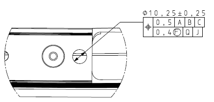
That is the offending tolerance, A,B & C are the overall datums for the whole part and I have no problems with that segment. The lower segment however to me is wrong in so many ways, maybe I am wrong as I am someone who is actually trained in ASME and not ISO, maybe he is right and it can be done like this in ISO,

He claims the F in the circle means measure in free state however ive never seen it placed where it is now. I also believe from my ASME training that the bottom segment refines the top segment so cannot use different datums, and I think this is the same for ISO.

I would usually argue my case louder but this is the senior design engineer here and he is digging his heels in at the moment and not changing the drawing, plus I don't want to look like an idiot if he is right and can tolerance the feature like this.

Anyone have any thoughts?
  • I think that you're correct in that the primary datum has to be the same for both segments. Don't quote me on that though. I also think that if you use Xact measure, PC-DMIS won't even let you do this.
  • The lower segment is a refinement of the upper segment. The Datum should be the same as the upper segment. However this is ASME and not ISO so maybe there is a difference there. The upper is the Pattern locating tolerance zone and the lower is the feature relating tolerance zone, the lower is not located relative to datum reference frame and at minimum the lower must overlap the upper.
  • You might need to tap the infinite wisdom of the ISO Wizard

    I only know how very wrong it is in ASME-land. Upside down
  • Neither of these cases necessarily reflect your exact case, but are examples of where it could be driven from.

    |A|B|C| could be casting datums, want to insure positional integrity to the overall structure. |Q|J| could be machined dims, feature need be in position to that. Or |A|B|C| could be clamping points on a fixture, which could mean the feature is being distorted and the design requirement also requires it, in the free state, to be within 0.4 of other datums.

    I think it a bit odd, but allowable.
  • In these examples though, wouldn't the fcf be split with an upper and lower position symbol as opposed to just one symbol?
  • to me if one half is to the master datum system and the other is to the local datum system measured in free state then they need to be separate tolerances. with a note above the free state one stating this tolerance to be used when measured in free state.

    combining the two is just wrong and misleading.
  • The FCF should be split to two callouts as they don't share the same datums (a must for composite). I believe this is the exact same for ASME and ISO. PC-DMIS will throw a tantrum if you try to build this composite FCF in XactMeasure (because they have different datums). The (F) means in free state, which logically should apply to the upper segment as well (if they were two separate FCF's, this wouldn't be a problem).

    Also, the tolerance zone seems to be one-axis (non-cylindrical)...

    Good luck?
  • I would say he's right...
    I found this picture from a gdt article, which seems to be case close to yours. The article has been written for a well known teacher of gdt. (from ISO10579)

    What is strange on your dimension is that the tol is smaller in the free state than in the fixing state...

    In ISO standards, the first principle is the independancy of dimensions, so you can write the symbol in the same box without linking both dimensions...

    In your case, you should tell us where are Q and J from ABC.

    Another point : 8888 is a BS standard, not a ISO Slight smile. Maybe NB can confirm it or not ?
  • And I found this nice doc from Hexagon !

    The Role of Geometric Dimensioning & Tolerancing (GD&T) and How to Capitalise on its Value Proposition
    http://www.hexagonmi.com/solutions/technical-resources/technical-articles/the-role-of-geometric-and-tolerancing-and-how-to-capitalise-on-its-value-proposition

  • I would say he's right...
    I found this picture from a gdt article, which seems to be case close to yours. The article has been written for a well known teacher of gdt. (from ISO10579)
    {"data-align":"none","data-size":"medium","data-attachmentid":399558}

    Maybe the inclusion of the F meaning free state basically changes it into two different tolerances depending on how it is measured. So far I haven't found any reference as to how to use the F.

    What is strange on your dimension is that the tol is smaller in the free state than in the fixing state...

    The free state measurements are to a more local datum system so in theory there should be less error, but I also questioned the design engineer on this

    In ISO standards, the first principle is the independancy of dimensions, so you can write the symbol in the same box without linking both dimensions...

    In your case, you should tell us where are Q and J from ABC.

    Q is two points that control in the Y direction located at the top of the drawing I posted, J is three points locally around the hole controlling Z, No X control.

    Another point : 8888 is a BS standard, not a ISO Slight smile. Maybe NB can confirm it or not ?

    you are right that it is a BS standard BS EN ISO 8888, but also still ISO I believe?


    I cannot find an ISO definition, But ASME states that "unless otherwise stated all measurements are to be taken in a free state condition". Therefore if there is a note stating how to constrain the part but you want to measure a certain feature in free state you need to use the F modifier.

    Again that was in ASME so may not apply, but in my case there are no notes on the drawing stating how to measure or constrain the part, just an F on some features meaning measure this in free state. I would have measured all the features in free state as that is the only way to measure the parts on the CMM and get to all the features that need measuring. For me the designer has tried to have less tolerance in the Y direction compared to the X direction and so has created a local datum system. I cannot understand his thinking in this instance why he feels the need to split it up and create the FCF as he has done.

    for me I would have just written it like this, which maybe wrong but it gives him what he is asking for.

    |0.5|J|Q|C|
    |0.4|J|Q|