hexagon logo

Rant

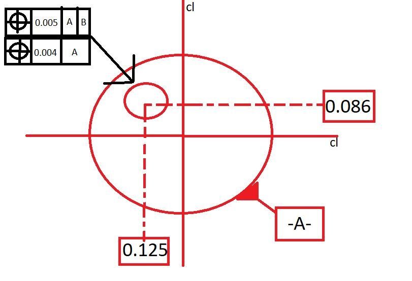
I have engineers here that have basic dimensions to control true position callouts-and they have true position callouts on those basic dimensions also!! They got upset cause i told them it makes no sense.. I have a hole with a TP .005 to A and B, and i have basic dimensions from A and B and then TP .004 of these dimensions to A.. How does that make sense?? how am i supposed to even inspect that ...but what do i know!!

AM I WRONG HERE???
  • I'm seeing your print like this:


    If my interpretation was correct, the only argument I would make would be that once you do out the math, you're allowed AT MAX 0.0017 deviation in each axis on the 0.005 TP.... so I would argue that the bottom composite frame should be 0.0017 OR LESS back to -A-. I'd make it 0.0015.
  • I'm seeing your print like this:

    {"alt":"Click image for larger version Name:\tpic grp.JPG Views:\t0 Size:\t36.8 KB ID:\t480350","data-align":"none","data-attachmentid":"480350","data-size":"full"}

    If my interpretation was correct, the only argument I would make would be that once you do out the math, you're allowed AT MAX 0.0017 deviation in each axis on the 0.005 TP.... so I would argue that the bottom composite frame should be 0.0017 OR LESS back to -A-. I'd make it 0.0015.


    Thank you so much for taking the time to explain!! i've taken a GD&T class but not this advanced. Since they couldn't explain to me how to inspect this-they just took it out of the drawing and made the hole true position tighter (.004 to A and B)
  • Happy to help!

    If the composite DRF that I shared above is what I was working with, I would do this:

    LOADPROBE/7107_Y_3X40
                TIP/T1A0B0, SHANKIJK=0, 0, 1, ANGLE=0
    MAN_PLN1   =FEAT/CONTACT/PLANE/DEFAULT,CARTESIAN,NONE,LEAST_SQR
                THEO/<0,0,0>,<0,0,1>
                ACTL/<0,0,0>,<0,0,1>
                TARG/<0,0,0>,<0,0,1>
                ANGLE VEC=<1,0,0>,RADIAL
                SHOW FEATURE PARAMETERS=NO
                SHOW CONTACT PARAMETERS=NO
    MAN_CIR1   =FEAT/CONTACT/CIRCLE/DEFAULT,CARTESIAN,OUT,LEAST_SQR
                THEO/<0,0,-0.1>,<0,0,1>,1,0
                ACTL/<0,0,-0.1>,<0,0,1>,1,0
                TARG/<0,0,-0.1>,<0,0,1>
                START ANG=0,END ANG=360
                ANGLE VEC=<1,0,0>
                DIRECTION=CCW
                SHOW FEATURE PARAMETERS=NO
                SHOW CONTACT PARAMETERS=NO
    MAN_CIR2   =FEAT/CONTACT/CIRCLE/DEFAULT,CARTESIAN,IN,LEAST_SQR
                THEO/<-0.086,0.125,-0.1>,<0,0,1>,0.2
                ACTL/<-0.086,0.125,-0.1>,<0,0,1>,0.2
                TARG/<-0.086,0.125,-0.1>,<0,0,1>
                START ANG=0,END ANG=360
                ANGLE VEC=<1,0,0>
                DIRECTION=CCW
                SHOW FEATURE PARAMETERS=NO
                SHOW CONTACT PARAMETERS=NO
    MAN_LIN1   =FEAT/LINE,CARTESIAN,UNBOUNDED,NO
                THEO/<0,0,-0.1>,<-1,0,0>
                ACTL/<0,0,-0.1>,<-1,0,0>
                CONSTR/LINE,OFFSET
                SURFACE NORMAL = <0,0,1>,MULTI POINT
                ID = MAN_CIR1,MAN_CIR2,,
                OFFSET = 0,0.125
    A1         =ALIGNMENT/START,RECALL:STARTUP,LIST=YES
                  ALIGNMENT/LEVEL,ZPLUS,MAN_PLN1
                  ALIGNMENT/ROTATE,XMINUS,TO,MAN_LIN1,ABOUT,ZPLUS
                  ALIGNMENT/TRANS,XAXIS,MAN_CIR1
                  ALIGNMENT/TRANS,YAXIS,MAN_CIR1
                  ALIGNMENT/TRANS,ZAXIS,MAN_PLN1
                ALIGNMENT/END
                MODE/DCC
                CLEARP/ZPLUS,PLN_A.Z+0.5,ZPLUS,PLN_A.Z+0.5,ON
    PLN_A      =FEAT/CONTACT/PLANE/DEFAULT,CARTESIAN,NONE,LEAST_SQR
                THEO/<0,0,0>,<0,0,1>
                ACTL/<0,0,0>,<0,0,1>
                TARG/<0,0,0>,<0,0,1>
                ANGLE VEC=<1,0,0>,RADIAL
                SHOW FEATURE PARAMETERS=NO
                SHOW CONTACT PARAMETERS=NO
    CIR_B      =FEAT/CONTACT/CIRCLE/DEFAULT,CARTESIAN,OUT,LEAST_SQR
                THEO/<0,0,-0.1>,<0,0,1>,1,0
                ACTL/<0,0,-0.1>,<0,0,1>,1,0
                TARG/<0,0,-0.1>,<0,0,1>
                START ANG=0,END ANG=360
                ANGLE VEC=<1,0,0>
                DIRECTION=CCW
                SHOW FEATURE PARAMETERS=NO
                SHOW CONTACT PARAMETERS=NO
    CIR1       =FEAT/CONTACT/CIRCLE/DEFAULT,CARTESIAN,IN,LEAST_SQR
                THEO/<-0.086,0.125,-0.1>,<0,0,1>,0.2
                ACTL/<-0.086,0.125,-0.1>,<0,0,1>,0.2
                TARG/<-0.086,0.125,-0.1>,<0,0,1>
                START ANG=0,END ANG=360
                ANGLE VEC=<1,0,0>
                DIRECTION=CCW
                SHOW FEATURE PARAMETERS=NO
                SHOW CONTACT PARAMETERS=NO
    CNC_LIN1   =FEAT/LINE,CARTESIAN,UNBOUNDED,NO
                THEO/<0,0,-0.1>,<-1,0,0>
                ACTL/<0,0,-0.1>,<-1,0,0>
                CONSTR/LINE,OFFSET
                SURFACE NORMAL = <0,0,1>,MULTI POINT
                ID = CIR_B,CIR1,,
                OFFSET = 0,0.125
    A2         =ALIGNMENT/START,RECALL:STARTUP,LIST=YES
                  ALIGNMENT/LEVEL,ZPLUS,PLN_A
                  ALIGNMENT/ROTATE,XMINUS,TO,CNC_LIN1,ABOUT,ZPLUS
                  ALIGNMENT/TRANS,XAXIS,CIR_B
                  ALIGNMENT/TRANS,YAXIS,CIR_B
                  ALIGNMENT/TRANS,ZAXIS,PLN_A
                ALIGNMENT/END
    DIM LOC3= LOCATION OF CIRCLE CIR1  UNITS=IN ,$
    GRAPH=OFF  TEXT=OFF  MULT=10.00  OUTPUT=BOTH  HALF ANGLE=NO
    AX    NOMINAL       +TOL       -TOL       MEAS        DEV     OUTTOL
    D       0.2000     0.0025     0.0025     0.2000     0.0000     0.0000 ----#----
    END OF DIMENSION LOC3
    DIM LOC1= POSITION OF CIRCLE CIR1  UNITS=IN ,$
    GRAPH=OFF  TEXT=OFF  MULT=10.00  OUTPUT=BOTH  FIT TO DATUMS=OFF  DEV PERPEN CENTERLINE=OFF  DISPLAY=DIAMETER
    AX    NOMINAL       +TOL       -TOL      BONUS       MEAS        DEV     OUTTOL
    X     -0.0860                                     -0.0860     0.0000           
    Y      0.1250                                      0.1250     0.0000           
    TP        RFS     0.0050                0.0000     0.0000     0.0000     0.0000 #--------
    END OF DIMENSION LOC1
    A3         =ALIGNMENT/START,RECALL:STARTUP,LIST=YES
                  ALIGNMENT/LEVEL,ZPLUS,PLN_A
                  ALIGNMENT/ROTATE_CIRCLE,XMINUS,TO,CIR_B,AND,CIR1,ABOUT,ZPLUS
                  ALIGNMENT/TRANS,XAXIS,CIR_B
                  ALIGNMENT/TRANS,YAXIS,CIR_B
                  ALIGNMENT/TRANS,ZAXIS,PLN_A
                ALIGNMENT/END
    DIM LOC2= POSITION OF CIRCLE CIR1  UNITS=IN ,$
    GRAPH=OFF  TEXT=OFF  MULT=10.00  OUTPUT=BOTH  FIT TO DATUMS=OFF  DEV PERPEN CENTERLINE=OFF  DISPLAY=DIAMETER
    AX    NOMINAL       +TOL       -TOL      BONUS       MEAS        DEV     OUTTOL
    X     -0.1517                                     -0.1517     0.0000           
    TP        RFS     0.0004                0.0000     0.0000     0.0000     0.0000 #--------
    END OF DIMENSION LOC2


  • Shouldn't CIR_B be a cylinder? Can a circle be a datum?
    And A is actually the OD and B is the plane
  • F8ck sorry I don't know how my brain got all crisscrossed like that

    Yes -B- should be a cylinder

    Level thru -B-
    rotate the same way I did
    XY origin is -B-
    Z origin is -A-

    Yes a cirxle can be a datum but it shouldn't be for your circumstance. I'm sorry
  • it's good-i get what you're saying. I mostly use Exact but i still do my alignments properly even though it's not necessary with exact. Thanks again Slight smile
  • I don't use XACT. Obviously it works but I prefer to have a higher level of control over my programs by making my own alignments and recalling them when i dimension stuff.
  • i was mostly taught exact. Legacy i only learned from this forum. I use it too but i'm more comfortable with exact