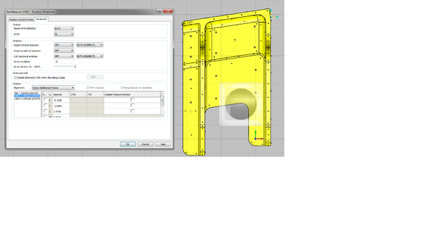
2 questions for measuring the 2x .5247 +.0007/-.0000 holes to datums D-A-B
*The holes are NOT inline with Datum -B-
#1 how does PC-DMIS calculate where the Datum origin is calculated from?
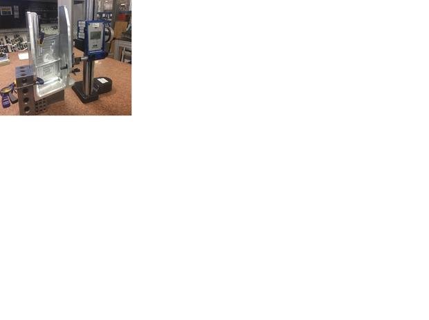
#2 how would you duplicate this manually with height gage and rock?