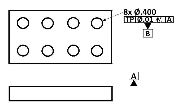
Print calls a plane Datum A , Datum B is a rectangular 2x4 pattern of holes thru plane A.
then there are a bunch of other features that call TP to A and B.
Searching the forum I figured out how to do a best fit alignment.
I'm stuck on how to set holes as B with DATDEF for use in a true position dimension (using Xactmeasure, PCDMIS 2016).
After you made your best fit alignment over the 8 holes you select a workplane , for example Xplus.
Open Constructed feature and select plane. Don't select an element only select Alignment and create it.
This plane you made you select for the DATDEF in X direction.
Same for Y and Z direction.
Why make it complicated when XactMeasure does it for you? Creating datums from the alignment is OK if the drawing says so (mostly by using [XYZ ] in ISO-land), but be careful with other datum combinations...
ok so can we revisit BOLT PATTERNS as Datums?
I have a diametrical equispaced bolt pattern that is creating the central axis for a part.
other features are clocked to this bolt pattern. How do you construct a feature set for the bolt pattern so that PCDMIS reads it as both the origin and clocking datum?
If you're using XactMeasure (PC-DMIS 4.0 - 2020 R1) then you need to construct a set from your holes and then define the set as a datum.
If you're using the Geometric Tolerance command (2020 R2 - current release) you simply go into the datum definition dialog, select all the holes that make up the pattern and then define the datum letter.
If you're trying to do it using legacy dimensioning, you would need to create an alignment that does a best-fit to the hole pattern but you would not be able to include MMB/LMB.