hexagon logo

Legacy dimension - profile of a surface

First of all, I am aware this topic has been covered, but my google-fu failed to find a solution for my current conundrum.

All that follows is relative to PC-DMIS 2012

Part setup:
Datum A: Cylinder along Z, locking X, Y and two rotational DoF
Datum B: Plane perpendicular to A, locking Z
Datum C: Plane perpendicular to B at 5.5 basic from A's axis, locking the last rotational DoF

Callout:
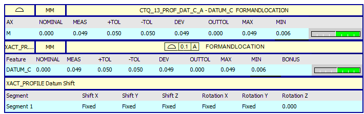
Profile of a surface of datum C relative to datum A

The issue:
While this is pretty straightforward to do with exact dimensions, the report template at my current workplace plays nicely only with legacy dimensions.
The result of legacy profile of a surface (form and position, LSQ best fit) while aligned to ABC are different (worse) than exact above.
To my understanding this is to be expected as legacy "form and location" fits to the current alignment, which is restricting 6 DoF instead of just 4 as Datum A alone would.
If this is the case, is there any way to use legacy with the callout that I have?
  • ACT_PROFILE: MAX 0.049 MIN 0.006 MEAS 0.049

    For the fit, I don't have VECTOR_MIN_MAX as an option ii have:

    LEAST_SQR: (Legacy MAX 0.050 MIN 0.002 MEAS 0.050, best fit alignment shows a deviation of 0.034)
    VECTOR_LST_SQR: (Legacy MAX 0.053 MIN 0.017 MEAS 0.053, best fit alignment shows a deviation of -0.034)
    MIN/MAX: (Legacy MAX 0.050 MIN 0.002 MEAS 0.050, best fit alignment shows a deviation of 0.034)
  • , I just sent you a private message with a link for you to upload your .prg & .cad. If you can send me the program I will be able to investigate further and let you know what is going on. The results should be identical using the method I described so I need to dig a little deeper to find out why they are not.

  • OK, so I found out what was going on. Your datum C plane is a constructed plane made up of several vector points. When the plane is referenced for the bestfit alignment, only the centroid is being used. If you construct a feature set from the datum C points and reference that in the bestfit alignment instead, the legacy and Xact numbers match. It looks like the Xact bestfit is a little more intelligent than the bestfit option in an alignment and takes into account all of the individual hits rather than just the centroid.

    This is the change I made to the code...
    SCN5 =FEAT/SET,CARTESIAN
    THEO/<0,-5.5,-22.5>,<0,0,1>
    ACTL/<0.035,-5.534,-22.56>,<0.0000206,0.0004782,0.9999999>
    CONSTR/SET,BASIC,DATC_1,DATC_2,DATC_3,DATC_4,DATC_5,DATC_ 6,DATC_7,DATC_8,DATC_9,DATC_10,,
    ALN_PROFILE=ALIGNMENT/START,RECALL[emoticon:6D505171FAA4497C85C5CA27290C555D]ATUM_ABC,LIST=YES
    ALIGNMENT/LEVEL,ZPLUS,DATUM_A
    ALIGNMENT/TRANS,XAXIS,DATUM_A
    ALIGNMENT/TRANS,YAXIS,DATUM_A
    ALIGNMENT/BF2D,ZMINUS,MIN/MAX,CREATE WEIGHTS=NO,ROTONLY,0,0,0,0.3
    ITERATEANDREPIERCECAD=YES,TOLERANCE=20,MAX ITERATIONS=100
    Deviation Threshold=0.2
    SHOWALLINPUTS=YES,SHOWALLPARAMS=YES
    ID=SCN5,Feature Sets,,1,YES
    DATC_1,Points,,1,YES
    DATC_2,Points,,1,YES
    DATC_3,Points,,1,YES
    DATC_4,Points,,1,YES
    DATC_5,Points,,1,YES
    DATC_6,Points,,1,YES
    DATC_7,Points,,1,YES
    DATC_8,Points,,1,YES
    DATC_9,Points,,1,YES
    DATC_10,Points,,1,YES
    ID=
    ALIGNMENT/END
    DISPLAYPRECISION/5
    DIM CTQ_13_PROF_DAT_C_A= PROFILE OF SURFACE OF PLANE DATUM_C FORMANDLOCATION UNITS=MM ,$
    GRAPH=OFF TEXT=ON MULT=100.00 ARROWDENSITY=100 OUTPUT=BOTH
    AX NOMINAL MEAS +TOL -TOL DEV OUTTOL MAX MIN
    M 0.00000 0.04895 0.05000 0.05000 0.04895 0.00000 0.04895 0.00577 ---|---#
    XACT_PROFILE =SURFACE PROFILE : DATUM_C
    FEATCTRLFRAME/SHOWPARAMS=YES,SHOWEXPANDED=YES
    CADGRAPH=POSITION,REPORTGRAPH=OFF,TEXT=BOTH,MULT=1 00.00,ARROWDENSITY=100,OUTPUT=BOTH,UNITS=MM
    COMPOSITE=NO,
    CUSTOMIZED DRF=NO
    STANDARDTYPE=ASME_Y14_5
    PRIMARY DIMENSION/PROFILE OF SURFACE,0.1,<UZ>,<UTol>,A,<MC>,<dat>,<dat>
    NOTE/XACT_PROFILE
    FEATURES/DATUM_C,,
    IF/CTQ_13_PROF_DAT_C_A.OUTTOL<>0
    ASSIGN/OUTTOL_TOT=OUTTOL_TOT+1
    END_IF/
    DISPLAYPRECISION/3


    Since you have a CAD model, I also turned on iterate and re-pierce since this will also improve the accuracy.
  • I am not sure what I am missing, but I am getting very different results (same base data as the program sent earlier)

    DATC_SET =FEAT/SET,CARTESIAN
    THEO/<0,-5.5,-22.5>,<0,0,1>
    ACTL/<0.038,-5.534,-22.559>,<0,0,1>
    CONSTR/SET,BASIC,DATC_1,DATC_2,DATC_3,DATC_4,DATC_5,DATC_ 6,DATC_7,DATC_8,DATC_9,DATC_10,,
    ALN_PROFILE=ALIGNMENT/START,RECALL[emoticon:6D505171FAA4497C85C5CA27290C555D]ATUM_ABC,LIST=YES
    ALIGNMENT/LEVEL,ZPLUS,DATUM_A
    ALIGNMENT/TRANS,XAXIS,DATUM_A
    ALIGNMENT/TRANS,YAXIS,DATUM_A
    ALIGNMENT/BF2D,ZMINUS,MIN/MAX,CREATE WEIGHTS=NO,ROTONLY,0,0,0,719.989
    ITERATEANDREPIERCECAD=YES,TOLERANCE=20,MAX ITERATIONS=100
    Deviation Threshold=0.2
    SHOWALLINPUTS=YES,SHOWALLPARAMS=YES
    ID=DATC_SET,Feature Sets,,1,YES
    DATC_1,Points,,1,YES
    DATC_2,Points,,1,YES
    DATC_3,Points,,1,YES
    DATC_4,Points,,1,YES
    DATC_5,Points,,1,YES
    DATC_6,Points,,1,YES
    DATC_7,Points,,1,YES
    DATC_8,Points,,1,YES
    DATC_9,Points,,1,YES
    DATC_10,Points,,1,YES
    ID=
    ALIGNMENT/END
    DISPLAYPRECISION/5
    DIM CTQ_13_PROFILE_DAT_C= PROFILE OF SURFACE OF PLANE DATUM_C FORMANDLOCATION UNITS=MM ,$
    GRAPH=OFF TEXT=OFF MULT=10.00 ARROWDENSITY=100 OUTPUT=BOTH
    AX NOMINAL MEAS +TOL -TOL DEV OUTTOL MAX MIN
    M 0.00000 0.05266 0.05000 0.05000 0.05266 0.00266 0.05266 0.01708 ---|--->
    XACT_PROFILE =SURFACE PROFILE : DATUM_C
    FEATCTRLFRAME/SHOWPARAMS=YES,SHOWEXPANDED=YES
    CADGRAPH=OFF,REPORTGRAPH=OFF,TEXT=OFF,MULT=1.00,AR ROWDENSITY=100,OUTPUT=BOTH,UNITS=MM
    COMPOSITE=NO,
    CUSTOMIZED DRF=NO
    STANDARDTYPE=ASME_Y14_5
    PRIMARY DIMENSION/PROFILE OF SURFACE,0.1,<UZ>,<UTol>,A,<dat>,<dat>
    NOTE/XACT_PROFILE
    FEATURES/DATUM_C,,
  • I just tried it again with the program you sent me (didn't save any changes earlier) and I get the same results for legacy and XactMeasure. This is the sequence I followed when edit
    1. Open routine and put cursor immediately prior to the ALN_PROFILE alignment.
    2. INSERT>FEATURE>CONSTRUCTED>SET. Select points DATC_1 thru DATC_10 and hit create.
    3. F9 ALN_PROFILE alignment, select the line that says "2D bestfit about ZPLUS to 1 feature" and then click the BestFit button.
    4. Deselect DATUM_C from feature list and select SCN5 (my constructed set) instead. Turn on iterate & Re-pierce, make sure all other options are correct, click "compute" then OK.
    5. Click OK on the main alignment dialog screen and select "NO" when asked if I want to update nominals.
    6. In the Legacy Profile (DIM_CTQ_13) overtype part of the DATUM_C feature name to force the command to update.
    7. Put the cursor on the XactMeasure profile command (XACT_PROFILE) and compare the values shown in the status window with the legacy results displayed in the edit window command.
    Results


    Attached Files
  • Than you for the detailed instructions.
    I followed them but I am still getting discrepancies between Legacy and Xact.

    I rerun the program to make sure (on a different part) and I am seeing Min/Max of -.0.14/-0.049 for Legacy VS -.0.16/-0.048 for Xact

    Since you worked on 2012 R1 as well, do you think this might be related to some difference in PC-DMIS settings?
  • It could be related to the UseSizeForProfileDimensions registry setting maybe. There was a change to the 2009 version of the ASME Y14.5 standard which meant that size should be taken into account when reporting a form only legacy profile dimension. The UseSizeForProfileDimensions registry setting is essentially a switch that allows the user to revert to pre 2009 behaviour. If set to 0 profile calculations do not take size into account (as per ASME Y14.5 1994), if set to 1 they do (As per ASME Y14.5 2009 onwards). The only other thing I can think of is if the bestfit type is not the same for both calculations or if there is a difference between my version of PC-Dmis and yours. I am only able to install as far back as PC-Dmis 2013 on my laptop since older versions are not compatible with windows 10 - they give an "unsupported operating system" error and abort if you try to install.
  • For the alignment, try doing the best fit portion just to the individual Datum C points, everything else the same. (Instead of a plane or feature set.)
  • Must be a new thing. I have PC-DMIS 2012 MR1 installed on both of my Windows 10 machines from before we updated to 2017.
  • Changing UseSizeForProfileDimensions causes the dimension to change if the best fit is done with a set or individual points, but no difference if the plane is used. None of the results corresponds to Xact.

    Regarding VinniUSMC's suggestion, using the individual points causes yet another change in the result, but it still does not align with Xact.

    My issue is that I have several sets of values (Xact, Legacy with various different settings combination for the alignment's best fit) that should be substantially equivalent but show rather large differences (up to 0.015mm on a small sample size, so larger discrepancies would not surprise me on bigger data sets) and I have no idea which one to trust.