
I haven't used legacy before and need help on how to measure/report these composite true positions using it.
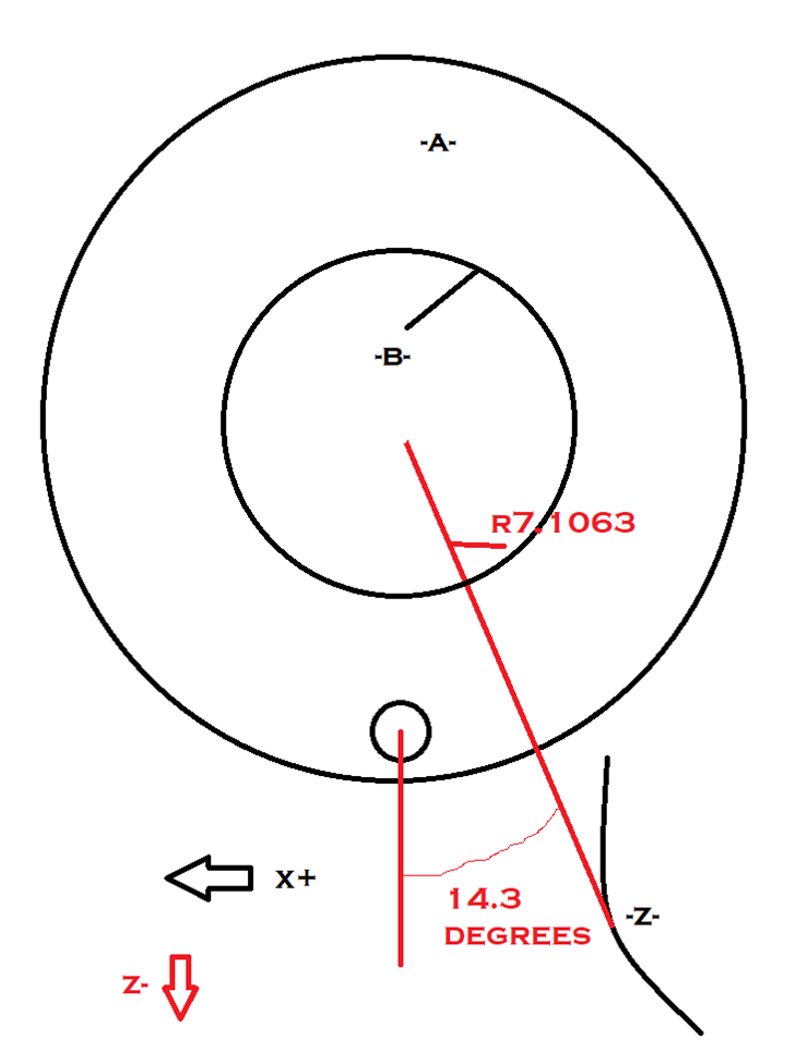
Datum A is a surface
Datum B is a bore
Datum C is a bore
I have my alignment set up to ABC.
In TP#1 how do I ignore C to get the AB alignment?
and how do I get just B for the composite?
In TP#2 How do I get the composite with no datums?
Can Legacy do MMC bonus or MMB datum shifts?
TP #1:
{"data-align":"none","data-size":"medium","data-tempid":"temp_22355_1648740249085_596"}

TP #2:
{"data-align":"none","data-size":"medium","data-tempid":"temp_22356_1648740215078_727"}


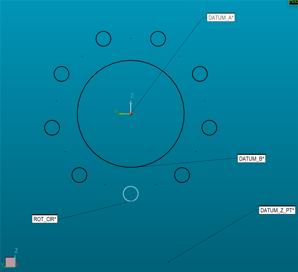 updated graphic