hexagon logo

tie features to existing features

greetings,

i've got .064" tip grooves that were machined before the tips were straightened for true position. of course i'm having troubles with the parts running on the cmm. the plane circle path of the slots making most of the trouble...

i've tried to tie the groove circle plane target locations (x,y,z) and rotations (i,j,k) to previously probed features. PLN_512 (used for the Y location) is the back side of the tip (right side in the pic) and CYL_181 (used for the X and Z) is the adjacent cylinder (just to the left of PLN_512).

it doesnt seem to be working as well as i'd hoped. the probe still occasionally contacts the side of the slots when probing the circle planes for the slot both when approaching the part and when moving from one touch point to the next indicating the Y axis math is not being done and/or the circle path is not canted with the same IJK as PLN_512.

am i missing something?
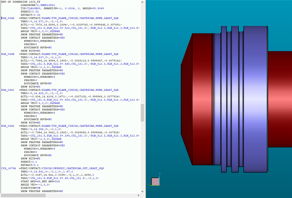


  • so looking at say PLN_064A target values can you see any reason why they wouldn't work out?

    is there an additional box somewhere i should be checking etc...?
  • so looking at say PLN_064A target values can you see any reason why they wouldn't work out?

    is there an additional box somewhere i should be checking etc...?


    If I'm reading your code right. PLN_64A and PLN_64B are .064in apart and should have opposing vectors. However, your assignments are giving both of them a J-Vector assignment of PLN_512.J. It seems like one of those should be negative.
  • oh damn!!! youre right!! PLNA is the left side of the far left slot... PLNB is the right side of the far left slot. same with PLNC and PLND... PLN_512 has a -Y vector

    i guess the solution would be to change the J vector to "PLN_512.-J" to flip the vector?

    the funny part is it seems to be working out as it is... or at least in some cases... which is even stranger. by that i mean the probe approach directions are working, its just a matter of clearance that seems to be the issue (approaching too close to the edge of the plane, but on the correct side)
  • "PLN_512.-J" won't be recognized by the software. But "-PLN_512.J" would work.
  • Auto-plane relies on your spacer value, even though you update the centroid and linear location it could allow for touches outside the desired location. (Current instance, hit in the fillet radius or just catch the outer edge of your diameter, maybe both if the features aren't actually concentric.)

    You can have the points shift polar radial distance and linear distance easily with your pre-existing features, this would eliminate concern of touching an incorrect surface. You get to control how it would adjust.