hexagon logo

I don't understand Work Planes

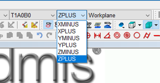
Believe it or not, I've been programming in PC-DMIS for over 10 years now and I still don't understand Work Planes. I've always figured a way around it and told myself I'd learn it later when I had time.

I was having trouble with something today and finally asked a co-worker for help. He saw what I was trying to do, changed the work plane and everything's fine.

Can someone explain it to me???
  • It's how the machine sees it and in fact, how you see it if you were holding the part in your hand.

    X+ the right side
    X- the left side
    Y+ the back side
    Y- the front side
    Z+ the top side
    Z- the bottom side​
  • It really only applies to certain aspects of your program. MOVEPLANES , dimensions / distance , measured features ( Auto features dont care ) are a few things that come to mind. Isnt figure that out easier than figuring out work arounds ? Slight smile
  • This is why I still have the little cube they gave us in classes they have the work planes on em so I don't have to think. Slight smile
  • Imagine having a cube and want to measure the distance between the left side and right side. You probe the 2 planes and you create a distance measurement. If your workplane is Z axis or Y axis the machine can "see the line" connecting this 2 planes and can measure it. If you define the workplane as X is like the machine is viewing the part from the sides and instead of seeing the connecting line, it sees a point and thus it cannot measure it.

    Other example... Imagine now that on the left side you want to create a measured circle probing with the joystick. You probe and construct a circle with workplane X selected. The machine will fit the circle on the points on that workplane. If you have the Y or Z workplane selected, it will try to create a circle on these sides (front side or top side accordingly) and will give you a circle with a crazy number of dia and center.

    When working with a CAD you don't actually really need to change it for probing matters, only in cases as my first example.
  • If you look at a circle from the proper workplane, it looks like a circle.

    If you look at a circle from improper workplane, 'the side', it looks like a line. A line that has the same length as the diameter of the circle, if you savvy.
  • Too bad Hexagon doesn't bother to spend a little more time on this topic in their training courses (which clearly is important) I got the same problem with iterative & best fit. Too little time to explain concepts that aren't exactly easy to get after one or two examples.
    If you have a part like a cube sitting on the CMM table with its primary datum pointing up if you want to probe holes drilled into its sides you need to change the workplane to either x plus/minus or y plus/minus. Z-plus is always the default.
  • think of it as the way the CMM is "looking" at the part. Lets say you have two points in mm [(0,0,0) and (10,0,0)] so they are 10mm different in the X axis.

    now if you were to look at these points in the X direction you would see this >>> . Could you tell how far apart they are? No you couldn't because one would be right behind the other and you wouldn't be able to determine how much distance was between them.


    now if you looked at them in the Y or Z axis you would see something like this>>> . . you can now quantify approximately how far apart those two points are.

    Workplanes work the same way. It allows the CMM to view the distance between the features without trying to look through them.

    Does that make sense?
  • Imagine if you will.... A cube or 1,2,3 block with holes, setting on the granite of a bridge machine.
    the top surface is Z+. A hole on the right or left sides would have a Y & Z location and the work plane is X.
    A hole facing or opposite front or rear sides would have a X & Z location and the work plane is Y.
    HTH