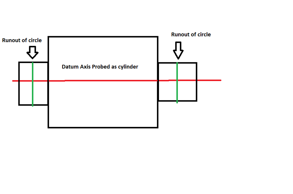
I have a part that is constantly out of tolerance on radial runout. My datum is a cylinder and my runout feature is a circle. When I change runout from from radial to axial, it’s now within tolerance.
I looked up radial runout and axial runout and the difference is radial is how far off a feature is off the datum axis but still parallel and axial is how much of a tilt the feature has to the datum axis. Which one should I use and why and I out of tolerance with only one and not both?
So here's an pic of what i'm checking. FYI, this program has been running on the CMM for 2 years and the parts were 95% good. Part was moved to a different CNC and now we are having out of tolerance problems on a daily basis. Not saying the CMM is perfect or even correct. Just pointing out the only change that has occurred.
The datum cylinder and the runout feature to the right are machined at the same time with a tail-stock installed. Then the part is taken out of the chuck and flipped around to chuck on the newly machined runout feature and then it machines the other runout feature, that feature is the one that almost always comes out of tolerance.
GD&T callout is Single Runout of 0.006" to datum A.
That makes sense. I though about checking my runout features as cylinders but there isn't exactly a lot of meat on them, my CMM head will hit other surfaces so I chose to stick with circles.
Are we talking circular runout vs total runout here? They are very similar to each-other..you measure them both the exact same way & collect the same data.. the way the final result is calculated is different depending on which one the print requires