Hello everyone,
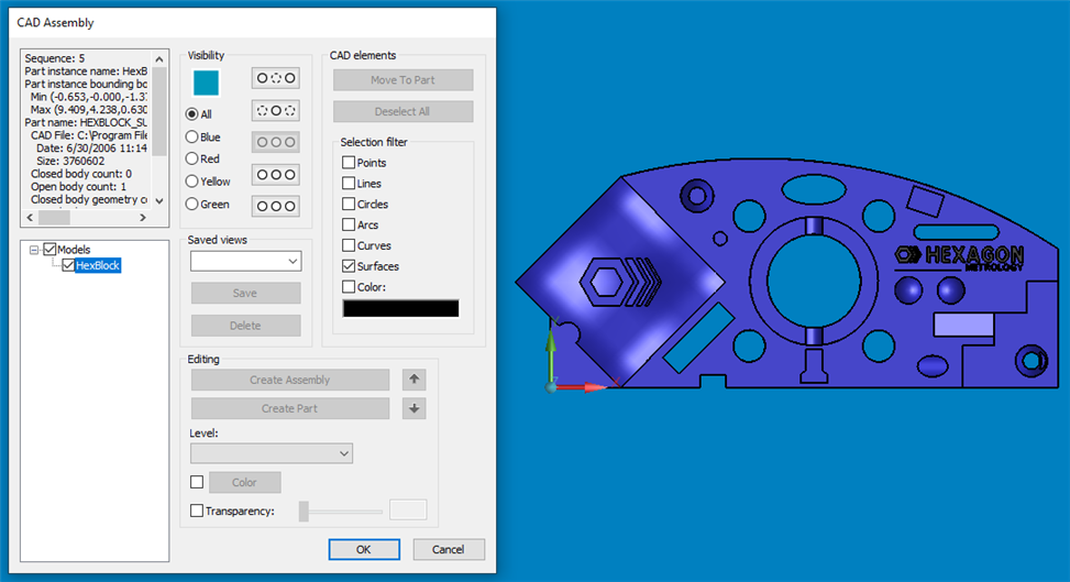
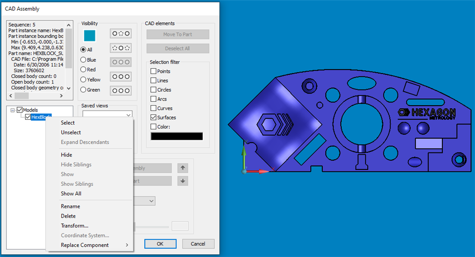
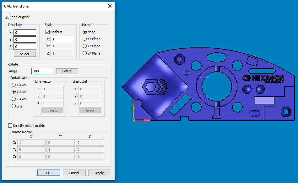
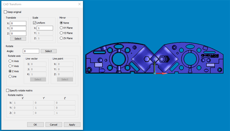
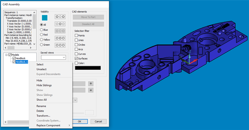
I would like to program a measuring routine in which the workpiece has to be re-clamped (top side first, then bottom side). Now I want the CAD model to rotate in the measurement routine after re-clamping, which will find the model shown with the measurement routine again. Can someone help me there?
One method of getting the model to flip in the graphics display window is to have two copies of the model in your measuring routine. One copy is transformed so the first side is up and one copy is transformed with the second side up. This can be done through the CAD Assembly dialog:
Working with Assemblies of Parts (hexagonmi.com). You can either import the model twice and let the software merge the copies together or transform the model while the 'keep original' box is checked - that makes a copy of whatever is being transformed.
At the beginning of your measuring routine, hide the second copy of the model so just the side 1 model is showing, create a viewset command, and recall that viewset. That will make the first model appear in the graphics display window while running the first side of the part. Then, when you begin programming the second side of the part, hide the 1st copy of the model and show the second copy. Create/recall a viewset for that arrangement and then the second model will show in the graphics display window.
I tried this and I can't get it to work. I got my original CAD model oriented how I want, then create VIEWSET1. Then, I transform my original CAD model, while checking the box "keep original". First, the copy doesn't rotate correctly when transformed. So I hide the original, then finish rotating the new copy into the correct orientation, then create VIEWSET2. When I go to recall VIEWSET1, it shows both models together. I think that when you transform, the models' transformations are not independent of each other, therefore by the time I transform other copies for a total of five different orientations, the original model is in some crazy orientation. I wish someone would do a video on this, because I can't seem to get it.
dcoss, It sounds like you have the main idea and are mostly there. The problems you may be having with transforming the models is that each model needs to be done from the CAD Assembly dialog.
Here is how that is done. Below is the CAD Assembly dialog showing just one model in the Assembly Tree.
If you right click on an item it gives you a number of options, one of which is to Transform just that item. You can transform just one item at a time, or an assembly of items, or if you choose the item on the top of the model tree (Named 'Models' in this example), you can transform all of the models at once.
Here I am transforming just the one model. I checked the Keep original box so a copy is made during the transform operation. Then, click apply.
That one operation gives you this. I'll then click the OK button to close the Transform dialog. If you do any more tranformations at this time, it will affect the original model, not the copy.
To further transform the copy, you can do that from the CAD Assembly Dialog. You can see below there are now Two models. You can now transform just the second model by right clicking on it from the Assembly Tree. From here you can also change the color of each model, make one transparent, make copies of entire assemblies, or replace a single model without needing to re-transform it (provided the new model has the same origin).