hexagon logo

XactMeasure $#!*&$#!

There I times I hate this freaking POS tolerancing.

This is on one of the new jobs we are running. I ran the correlation/bias study (customer results vs. our results), the Type1 and GR&R on this same program and now when I run any more than one part (same part even) I get one position dimension reporting all fubared and does not even come close to what the actual feature measures. The dimensioning is done to meet the correlation/bias study, we have all results from this study, 3 parts ran 9 times without removing the part from the fixture then we compare our average of those with the customer's measurements (must meet 10% of feature tolerance).

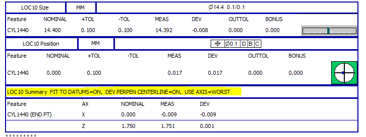
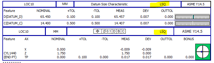
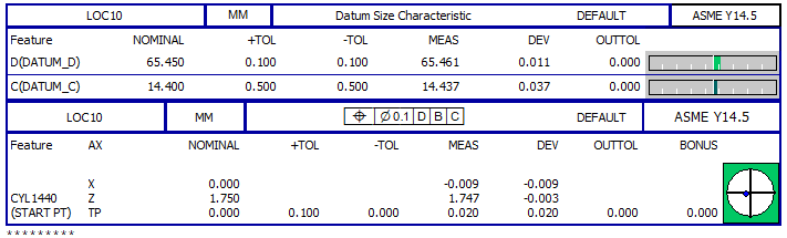
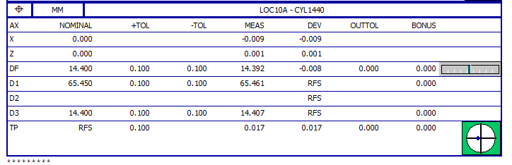
I am using a constructed circle from a thread locator measured as a cylinder and an offset plane (matches the customer program) and the feature actuals are well within tolerance and XactMeasure reports the first run as being where it should be but when I run this same part the second time without closing the DEMON is when the one feature (just this one, none others) tolerance jumps from .0038" TP to .017". I deleted the Xact tolerance and recreated it and it still does the same, first part is where it should be at .0038" and everything after goes to .017". I've dumped in legacy position and it does what it is supposed to do. If I quit the program and run the part again everything is as it should be (Online Mode or through Inspect) but if I run the same 2 or more time it takes a crap on me.

AHK_ALIGN  =ALIGNMENT/START,RECALL:STARTUP,LIST=YES
              ALIGNMENT/LEVEL,YMINUS,PL_A
              ALIGNMENT/ROTATE,ZMINUS,TO,PL_H,ABOUT,YPLUS
              ALIGNMENT/TRANS,XAXIS,PL_K
              ALIGNMENT/TRANS,YAXIS,PL_A
              ALIGNMENT/TRANS,ZAXIS,PL_H
            ALIGNMENT/END
THD_LAT_2  =FEAT/CIRCLE,CARTESIAN,OUT,YES
            THEO/<0.4565+0,-0.4,-0.9>,<0,-1,0>,0.197
            ACTL/<0.4581,-0.4,-0.8989>,<0.0018231,-0.9999928,-0.0033329>,0.1972
            CONSTR/CIRCLE,INTOF,THD_LAT_22,PL_A_OFFSET
BALLOON_40 =POSITION : THD_LAT_2
            FEATCTRLFRAME/SHOWNOMS=YES,SHOWPARAMS=YES,SHOWEXPANDED=YES,
            CADGRAPH=OFF,REPORTGRAPH=OFF,TEXT=OFF,MULT=10.00,ARROWDENSITY=100,OUTPUT=BOTH,UNITS=IN,
            COMPOSITE=NO,FIT TO DATUMS=NO,DEV PERPEN CENTERLINE=ON,OUTPUT ALIGNMENT=Current Alignment
            CUSTOMIZED DRF=NO
            STANDARDTYPE=CUSTOM
              PRIMARY DIMENSION/POSITION,DIAMETER,0.015,<MC>,A,H,K
              SECONDARY DIMENSION/,<tol>,<MC>,<dat>,<dat>,<dat>
              NOTE/BALLOON_40
            FEATURES/THD_LAT_2,,
            THD_LAT_2
             X:NOM=0.4565
             Z:NOM=0.9
            <NEW>
DIM REF_40A= POSITION OF CIRCLE THD_LAT_2  UNITS=IN ,$
GRAPH=OFF  TEXT=OFF  MULT=10.00  OUTPUT=BOTH  FIT TO DATUMS=OFF  DEV PERPEN CENTERLINE=OFF  DISPLAY=DIAMETER
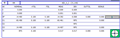
AX    NOMINAL       +TOL       -TOL      BONUS       MEAS     OUTTOL        DEV
X      0.4565                                      0.4581                0.0016
Z      0.9000                                      0.8989               -0.0011
TP        RFS     0.0150                0.0000     0.0038     0.0000     0.0038 --#------
END OF DIMENSION REF_40A


I've told the bosses that for these 4 threaded holes I am removing the Xact dimensioning and going with legacy dimensioning (it never fails for RFS) unless I can get it figured out. Before we submit FAL to the customer we have to supply them with all of the working inspection programs and I need to get this nailed down.

I'm open to any and all ideas.

TIA
Duane​
  • neil.challinor & sorry to highjack feel free to move to a new thread if need be.


    so why does xact measure automatically do this? (V2020R1)


    When datum math changed to lsq also matches xact and legacy (V2022.2)


    2022.2 datum math changed back to default is just a few micron different but also calculates from the start point vs the end.


    2022.2 legacy (cmm alignment is not to the DBC but to ABC) use datums on, fit to datums on, perpen to CL on, from worst end of axis.


    ​​​

    Attached Files


  • This is a huge topic and best addressed via training. Our GD&T for PC-DMIS course covers all of this in detail and talks about the differences between legacy, XactMeasure and Geometric Tolerance commands.

    Legacy dimensioning was added to PC-DMIS nearly 30 years ago and as such, is quite limited. You can only dimension a SINGLE considered feature at a time (no support for patterns) and it does not support simultaneity. The document I shared earlier explains how you can get different datum fitting behaviour, depending on the combination of settings, and applies to LEGACY DIMENSIONING only. Legacy Dimensioning relies on the user to interpret the drawing and to create the appropriate alignments, features and constructions to verify requirements. As such, it does not claim to be fully compliant to any standard.

    XactMeasure was introduced in version 4.1 of PC-DMIS (2006) and was really our first attempt to properly follow the standards. It attempted to support both ASME and ISO but was heavily biased towards ASME (only real difference for ISO was the single value for profile). The reason XactMeasure applies "FIT TO DATUMS=ON", "DEVIATION PERPENDICULAR TO CENTRELINE=ON" and " USE AXIS=WORST" by default is because that is the correct way to evaluate position according to the rules defined in ASME Y14.5 - that's why you have to change the selected standard to "custom" in order to override those settings. Although it was an improvement on the older, legacy dimensioning method, it was by no means perfect. There were a number of things it didn't support, it still used traditional alignment concepts when constructing datum reference frames and there was no real intelligence or error checking. Simultaneity was supported but required all of the commands to be unmarked and then grouped together in a new, simultaneous evaluation command.

    Geometric Tolerance commands were introduced in 2020 R2, COMPLETELY replacing Xactmeasure and employing an entirely new GD&T library. Although the dialog may look similar to XactMeasure, the two commands are entirely unrelated. Geometric Tolerance commands are the first for which we claim to be fully compliant to both ASME Y14.5 and ISO1101 - there are now significant differences between the two standards. Datum reference frames are built using a simulated hard gauge approach rather than traditional alignments. For the first time, we now have robust validity checks preventing the creation of invalid feature control frames. Simultaneity is fully supported and has been made much more user friendly. One other significant difference is that the Geometric Tolerance command recalculates based on the math types selected whereas XactMeasure and Legacy Dimensioning required you to select the appropriate fitting algorithm ​when measuring the features.


    The first two examples you've created are roughly equivalent because you have overridden the Geometric Tolerance math to use Least Squared. The fourth example gives a similar measured value to examples 1 & 2 but is based on a different alignment. Only the third example could be claimed to be truly "compliant" because it is using DEFAULT math (constrained L2 for ASME Y14.5).


  • This is a huge topic and best addressed via training. Our GD&T for PC-DMIS course covers all of this in detail and talks about the differences between legacy, XactMeasure and Geometric Tolerance commands.


    neil.challinor . That's kind of a understatement. I have taken the the Applied GD&T for PC-DMIS – ASME (21150-21-231-1) earlier this year and have access to the online presentation. Nowhere in chapter 8 is legacy used for any of the location / positional tolerances nor is there any discussion of it. In the training the instructor literally went page by page and did not want to discus anything that was not in black and white per say. We in the class could tell right away that the instructor was not comfortable teaching a GD&T class to 10 - 20 year experienced inspectors. I do not recall covering any topics on the differences besides chapter 3 slide 11 which mentions the usage of the "use datums" but doesn't describe why or why not, and Chapter 4 slide 11. (I bookmarked them in the Hexagon book I bought for quick reference) I will go back and take an in depth look at the online training. Can you provide and insight as to what chapters / slides discuss this besides the aforementioned? As we also discovered in training, chapter 5 slides 13 & 14 if you construct a Primary Datum A Constrained_L2 as per chapter 4 slide 13 it will not show up in Geotol when the the flatness is required to be dimensioned. Then there is a note on chapter 5 on slide 13 that "Flatness on a constructed primary datum plane is not a valid requirement" so for those of us that used the constructed method, we had to use legacy to dimension the flatness for a constructed primary L2 primary datum plane. This seemed a little contradictory to all of us in the class since we selected used the L2 constrain algorithm, and then the question was asked "if we use an "auto feature plane" The algorithm options are lsq or min sep. So when dimension distance (non geotol) after defining it as Datum A what math is being used and does this meet the standard" but again the instructor did not want to go beyond what was in the documented training. Again sorry for the hijack and feel free to move this as necessary.