hexagon logo

Tertiary Datum doesn't constrain any degrees of freedom?

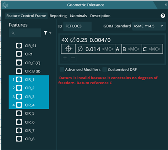
2023.1--Selecting Datum A as a plane; Datum B as a hole, Datum C as a hole.
"GEOMAJIC" States Datum C doesn't control any degree of freedom
Without Datum C, Datum B doesn't constrain the final degree of rotational freedom.
Am I wrong here?
  • What happens if you clean up the nominals of the circle to 0,1,0? Or is the hole actually at an angle?
  • -- Compund Datum A (curved)
    The holes are not 'true' to Datum A (but we are working to Y14.5-2009)
  • Okay, so if these features aren't nominally square, and indeed the datum a isn't nominally flat then iterative would probably be the technique to use.

    Are the datums defined as datum features or datum targets?

    If datum targets then use iterative, then create constructed alignment features (in effect a plane, line or point based off the current alignment) then assign these as datums for geo tol.

    Constructed plane - alignment (then change which axis so you could pick yplus/yminus to get A.

    Constructed line - alignment (then change axis for either X or z)

    Constructed point - origin to create a point at the origin for dat c.

    This is the required technique to dimension with geotol for an iteratively aligned part.
  • Wouldn't PC-DMIS utilize Datum C as basically a 'point'; considering Datum B constrain 2 axis of translation?
    PNT_A2 =FEAT/CONTACT/VECTOR POINT/DEFAULT,CARTESIAN
    THEO/<2.9783552,-0.0363233,-0.2755739>,<0,0.9991945,-0.0401288>
    ACTL/<2.9783552,-0.0363233,-0.2755739>,<0,0.9991945,-0.0401288>
    TARG/<2.9783552,-0.0113434,-0.2765771>,<0,0.9991945,-0.0401288>
    SNAP=NO
    SHOW FEATURE PARAMETERS=NO
    SHOW CONTACT PARAMETERS=NO
    PNT_A1 =FEAT/CONTACT/VECTOR POINT/DEFAULT,CARTESIAN
    THEO/<-2.9783575,-0.0363216,-0.2755718>,<0,0.9991945,-0.0401288>
    ACTL/<-2.9783575,-0.0363216,-0.2755718>,<0,0.9991945,-0.0401288>
    TARG/<-2.9783575,-0.0113418,-0.276575>,<0,0.9991945,-0.0401288>
    SNAP=NO
    SHOW FEATURE PARAMETERS=NO
    SHOW CONTACT PARAMETERS=NO
    PNT_A3 =FEAT/CONTACT/VECTOR POINT/DEFAULT,CARTESIAN
    THEO/<0.9997371,-0.0254643,-22.5902489>,<0,0.9995502,0.0299909>
    ACTL/<0.9997371,-0.0004756,-22.5894991>,<0,0.9995502,0.0299909>
    TARG/<0.9997371,-0.0004756,-22.5894991>,<0,0.9995502,0.0299909>
    SNAP=NO
    SHOW FEATURE PARAMETERS=NO
    SHOW CONTACT PARAMETERS=NO
    CIR_C =FEAT/CONTACT/CIRCLE/DEFAULT,CARTESIAN,IN,LEAST_SQR
    THEO/<0,0.000119,-22.6093018>,<-0.0000062,0.9995608,0.0296358>,0.25
    ACTL/<0,0.000119,-22.6093018>,<-0.0000062,0.9995608,0.0296358>,0.25
    TARG/<0,0.000119,-22.6093018>,<-0.0000062,0.9995608,0.0296358>
    START ANG=0,END ANG=360
    ANGLE VEC=<-1,-0.0000062,-0.0000001>
    DIRECTION=CCW
    SHOW FEATURE PARAMETERS=NO
    SHOW CONTACT PARAMETERS=NO
    CIR_B =FEAT/CONTACT/CIRCLE/DEFAULT,CARTESIAN,IN,LEAST_SQR
    THEO/<0,0,0>,<0.000003,0.9990898,-0.0426563>,0.25
    ACTL/<0,0,0>,<0.000003,0.9990898,-0.0426563>,0.25
    TARG/<0,0,0>,<0.000003,0.9990898,-0.0426563>
    START ANG=0,END ANG=360
    ANGLE VEC=<-1,0.000003,0>
    DIRECTION=CCW
    SHOW FEATURE PARAMETERS=NO
    SHOW CONTACT PARAMETERS=NO
    A4 =ALIGNMENT/START,RECALL:A3,LIST=YES
    ALIGNMENT/ITERATE
    PNT TARGET RAD=0.002,START LABEL=L1,FIXTURE TOL=0,ERROR LABEL=
    MEAS ALL FEAT=ALWAYS,MAX ITERATIONS=5,LEVEL AXIS=YAXIS,ROTATE AXIS=XAXIS,ORIGIN AXIS=ZAXIS
    LEVEL=PNT_A1,PNT_A2,PNT_A3,,
    ROTATE=CIR_B,CIR_C,,
    ORIGIN=CIR_B,,
    ALIGNMENT/END
    PLN_A =FEAT/PLANE,CARTESIAN,OUTLINE,NO,LEAST_SQR
    THEO/<0.3332449,-0.0327031,-7.7137982>,<0.0000003,0.9999999,0.0004866>
    ACTL/<0.333245,-0.0327031,-7.7137982>,<0.0000003,0.9999999,0.0004866>
    CONSTR/PLANE,BF,PNT_A1,PNT_A2,PNT_A3,,
    OUTLIER_REMOVAL/OFF,3
    FILTER/OFF,WAVELENGTH=0
    LIN_BC =FEAT/LINE,CARTESIAN,UNBOUNDED,NO
    THEO/<0,0.000119,-22.6093018>,<0,-0.0000053,1>
    ACTL/<0,0.000119,-22.6093018>,<0,-0.0000053,1>
    CONSTR/LINE,BF,3D,CIR_C,CIR_B,,
    OUTLIER_REMOVAL/OFF,3
    FILTER/OFF,WAVELENGTH=0
    A_ABC =ALIGNMENT/START,RECALL:STARTUP,LIST=YES
    ALIGNMENT/LEVEL,YPLUS,PLN_A
    ALIGNMENT/ROTATE,ZPLUS,TO,LIN_BC,ABOUT,YPLUS
    ALIGNMENT/TRANS,YAXIS,PLN_A
    ALIGNMENT/TRANS,XAXIS,CIR_B
    ALIGNMENT/TRANS,ZAXIS,CIR_B
    ALIGNMENT/END​
  • If the vector of Dat B was EXACTLY perpendicular to Dat A then Dat C would control the rotation.

    Because Dat B isn't exactly perpendicular, PC-Dmis sees it as having some amount of inclination (relative to Dat A) which would control the rotation.

    PD-Dmis doesn't differentiate between if it was at 90° or 0.00001°.


    In alignment terms, Pc-Dmis is doing this:

    A_ABC =ALIGNMENT/START,RECALL:STARTUP,LIST=YES
    ALIGNMENT/LEVEL,YPLUS,PLN_A
    ALIGNMENT/ROTATE,ZPLUS,TO,CIR_B,ABOUT,YPLUS
    ALIGNMENT/TRANS,YAXIS,PLN_A
    ALIGNMENT/TRANS,XAXIS,CIR_B
    ALIGNMENT/TRANS,ZAXIS,CIR_B
    ALIGNMENT/END​

    Can, May, Must - because Dat B Can control the Rotation, and it May, then it Must!

    I asked previously but you didn't answer - are the Datums defined by Datum symbols (little triangle on the feature or leader lines) or by Datum Targets (A1, A2, A3, B1, B2 C1 etc)​
  • It seems odd that the axis of the hole would have that small of a deviation from perpendicular to the -A- face. I'm thinking that the circle was extracted from the CAD model and there is a tiny modeling error in the CAD construction process. Those I,J,K values are tiny.
  • Both--
    Datum A Targets
    Datum B Hole
    Datum C Hole
  • I agree--But Model is the master. On these parts
  • So what do you do about this... Use the alternate method and construct basically everything?
  • Yes - iterative align, A1,A2,A3 Level, B&C rotate, B origin.

    Then construct alignment planes (and or lines/points - doesn't really matter as they're perfect features based on the current alignment which is created from the iterative alignment).

    Define those as datums in GeoTol.

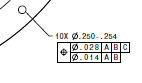
    Actually, that composite control frame looks a bit suss, ABC is fine, but in ASME the lower segment of a composite only controls orientation so I'm not sure what B is meant to do (in the lower segment).

    I'd assume it's meant to be two single segment control frames, but I'd seek clarification.