hexagon logo

using .2 and .3 probes for the first time

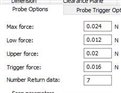
Hey Guys im having a lot of trouble trying to measure with .2mm and .3mm probes. Iv turned down the touch speed to 2 im not scanning. im only measuring small circles with 5 to 8 hits. It seems like I have to recalibrate them 1 to 2 times a day.
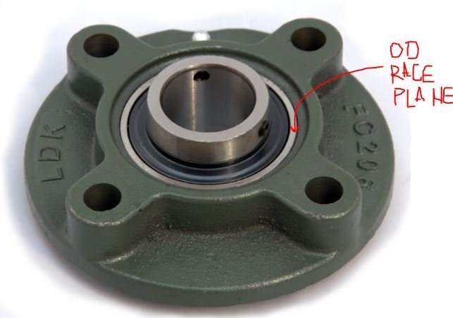
I have a large cylinder with flat bottom holes in its OD wall. In the holes are ball bearing that are pressed it. I only have a small amount of land available to measure the hole. I can measure 1 to 3 parts then I will start to have alarms saying the probe became unseated or that it couldn't retract. Usually once I calibrate it will work ok. Sometimes Ill have to recalibrate with the master probe. As you can imagine this is eating up a lot of time. If anyone has any advice I would appreciate it.
  • Drop touchspeed more. I use 1mm/sec with probes under 1mm diameter.
    What probe system are you using?
  • I have the HH-A-T2.5 head with the HP-S-X1H
  • Any other advice if the slowing down doesn't work?
  • here's my "Hexagon Systems Engineer" established values for probing parameters of my HP-S-X1H (on a Global S Chrome). Make sure yours are the same.

    Attached Files
  • So, you have a tiny amount of exposed shoulder on a cylinder wall, presumably limited between an outer extent of the part and the pressed-in bearing's outer race?
    I would be measuring a plane on the top surface of the bearing OD race,
    leveling and origin to the Bearing's OD race plane,

    -Doing this will eliminate the probe from dragging on the top surface of the bearing if it wasn't pressed-in perfectly square to whatever your current alignment is.-

    Then construct my hits for the circle you're trying to measure with 1/2 the ruby diameter plus 0.001" or so for clearance (0.3mm ruby is 0.0118" diameter) divide by 2, you get ~0.006" then add one thousandth for clearance. Measure the circle at 0.007" above the bearing's OD race plane.
    -If you've got more shoulder wall, bump it up 0.010" or more above the bearing plane.

    If that doesn't work, you can add a thousandth at a time until it does.
    -Or- If you run out of cylinder wall to move up (IE you are measuring a chamfer or are probing up the edge of the cylinder), you can play with your vector angle (instead of perfectly tangent to the cylinder, add 0.1 z vector away from bearing surface, so your prehit and retract are clearing the bearing with a tiny amount of z angle. Just know your measured diameter will have that amount of pythagorean's cosine error induced.
  • 1mm touch speed, and probe parameters in attached. You must calibrate with those settings in effect as well. Also, calibrate with "use Trax calibration" checked, PC-DMIS seems to apply bending forces uniformly in all directions, whereas a stylus will not behave that way, which will give you bizarre results on tiny styli.

    Attached Files
  • I'm calibrating now with all the new settings you guys sent. I will let you know how it goes. I went and rechecked the probe to make sure its square and straight to the machine axis and it was.

    lousid what do you mean by race plane?
  • Maybe I'm misinterpreting?
    You've got a bearing pressed into a cylindrical bore, of a larger component, correct?
    You are trying to assess the diameter of the cylindrical bore, in which the bearing is pressed in, correct?
    The bearing has an inner and outer race, correct?
    The planar "side" of the of the bearing has a flat surface on edges of inner and outer races, correct?
    The "Race Plane" I'm stating, is that exposed side edge of the bearing's outer race.
  • Like this. Level& origin to this plane, then measure the edges of your bore with just enough height to clear the probe.
  • Its just a ball bearing. Not a bearing like in your picture. But now I know what a race plane is so thank you.