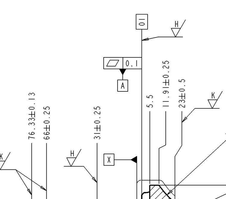
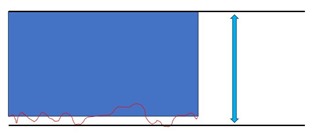
I've been doing some GD&T training lately and one thing that seems to complicate things for me is Rule #1 (aka the Envelope Principal). It states that at MMC, a feature must have perfect form and as it departs from MMC, a form error is allowed in the amount equal to the deviation from MMC. Unless there is a form callout that further refines and limits it. Say I have to add a flatness dimension for Datum A as shown below. The flatness comes in at 0.08, which is within tolerance. BUT there are at least 6 other features on this part that are dimensioned to Datum A. If the 23 +/- 0.5 for example measures at 23.45, that only allows me a form deviation of 0.05. The flatness is now out of tolerance. But how do I get PC DMIS to account for that? The flatness is still going to report in tolerance at 0.08, even though Rule #1 has now been violated. Worse yet, (and this is just rhetorical) how do I tell the shop supervisor that I have to reject his parts even though the flatness is reporting in tolerance when it's actually not?
Just to elaborate on what others have stated features of size must be outside to outside or inside to inside. Like a hole or a shaft. For example, a plane to another plane with the same vector is not a feature of size.
As has been stated, that's not a feature of size. It's 2 separate features. To be a feature of size it needs to be a width, with an inline dimension that connects each side and a size tolerance.
Your drawing is a linear dimension. Linear dimensions are normally checked by measuring the unrelated actual mating envelope (UAME), which in this case would be tangential planes that contact the 3 highest points of each plane, unconstrained to each other. Similar to putting one plane on a surface plate and measuring the highest points on the opposing plane to get a distance.
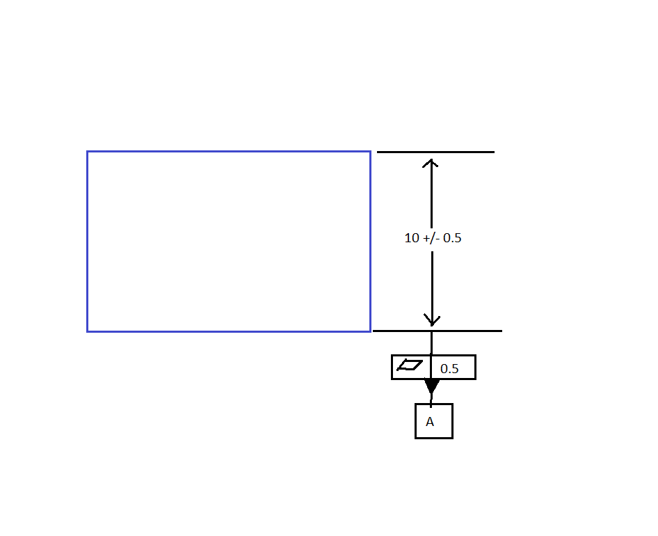
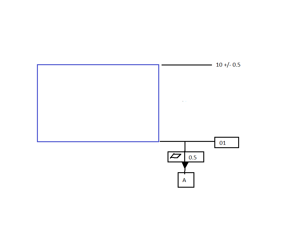
Ok, so here's two more rough sketches. Is the 1st one a feature of size and the 2nd one a linear dimension, even though the structure and dimensions of the part are the same? If both of them measured 10.4, then what would my flatness tolerance for each one be?
Flatness is measured independent of the size. You will be measuring the mating envelope of the sides. If it's an outside feature, you need to assume that something will be mating on the outside of the part. So you need to take your extreme points (3 point plane) for Datum A and the other side. The "dips" inside that mating envelope are calculated into your flatness, not the width. You don't lose width tolerance because the flatness.
Well it looks like I will have to ask the training providor for clarification because it seems from the general concensus of this thread, they're either giving me some misinformation or I'm just not understanding their lesson. I really want to show you the part that is tripping me up, but I don't want to get in hot water. Maybe I will ask them if I could screeshot and snip just that portion and post it here. In any case, I appreciate all the advice. I just want to make sure I understand this correctly because it should be a fairly basic concept.
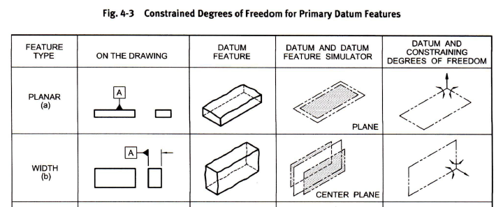
Your first example is a feature of size. Flatness applied to a width consisting of 2 parallel planes is measuring the derived median plane created by both sides. The size dimension is measuring the distance of 2 tangential planes separate of the flatness callout.
Your second example is not a feature of size. The flatness is measured only on the plane it's applied to. The size dimension is measuring the distance of 2 tangential planes separate of the flatness callout.
I think where you're getting hung up is the mating envelope principle. The mating envelope assures that parts assemble. The low spots on the outer planes have no effect on the mating envelope size. Nothing is normally contacting those surfaces.
If you wanted to control the form of the planes independent of the mating envelope you would use flatness, profile, etc. to control the form of the entire surface, either independently, or constrained to a Datum feature.
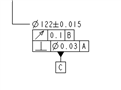
They gave me a quiz with a drawing very similar to this same sketch. They didn't call that surface out as a Datum, they just called it Surface A. I'm going to tell you their same question and answer, but substitute in my sketch dimensions. The way it's called out on the drawing though is the same.
Question: If the part was produced at 10.4, what is the maximum flatness error of Surface A?
Answer: 0.1 The print says that you can have a flatness tolerance of 0.5, so why is it now less? The answer is that you are allowed
up to 0.5 flatness tolerance. The part is still constrained by Rule#1 and the limits of size. If you only have 0.1 available before you reach the MMC size limit of the part, your max form error can only go to 0.1