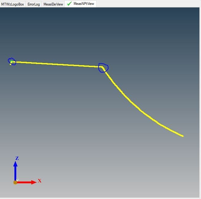
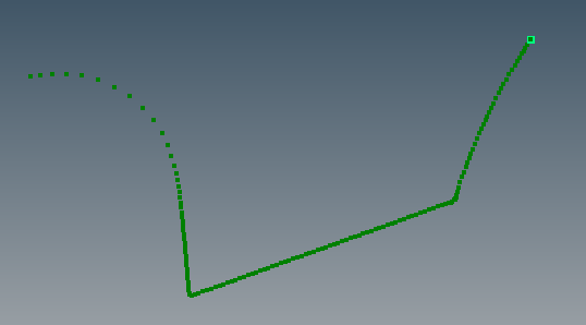
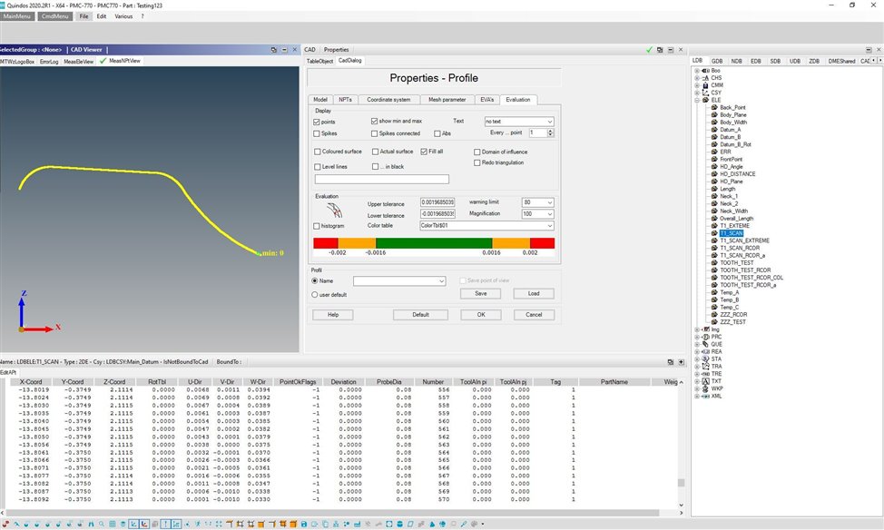
I'm looking to extract the maximum Z value and maximum ZX value from a scanned 2D curve. Attached is a screengrab of the curve. In this case, it would basically be the end-to-end points of the top line in the X direction. I've tried using FLEX2D, but get an error message 'Value too small (possibly two equal points) !' What's the best way to go about this ?
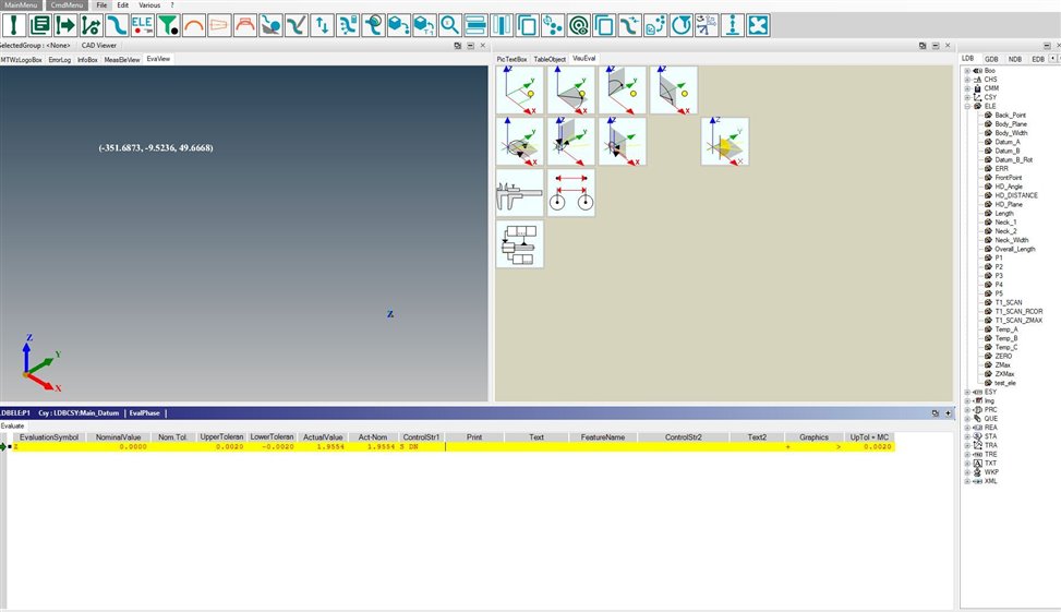
The highest Z value within the APT's of this scan is 2.1115. Using FXTREM, I'm getting 2.0846, which is the highest point at the very end of the scan. How can I get the highest Z and ZX values from an entire set of APT's?
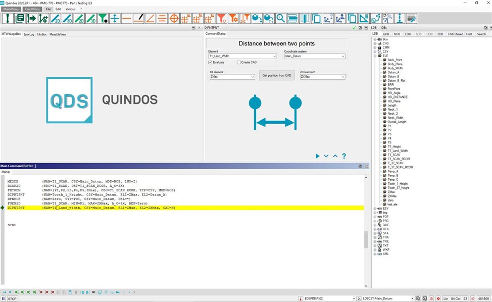
The max. in ZX is related to the radial distance of each point to zero, by the looks, so you need to do some programming to get the value. You must also be careful about the scan length, as you may find the last point in the scan using this method, as it is the most distant point from the origin. Try:
Using FXTREM for the ZMax, I'm still getting the value for the very end of the scan, not the highest Z point. See below. I'll try the ZX later and get back to you.
OK, I looked at the ZMax element data in the obj browser, and the correct ZMax value was displayed from the T1_SCAN_RCOR scan. Thank you! Now I'm on to find that ZX point...
As far as the ZX point, what I want to accomplish here is to evaluate the distance between the in the ZMax and the ZXMax point along the X axis. I tried the code you suggested, and am getting a distance of .0391", when the distance is actually about .125" measured manually. Am I missing something here...? One other thing... I tried using T1_SCAN_RCOR instead of T1_SCAN with FGEX2D and I get an error saying "No extreme point found".
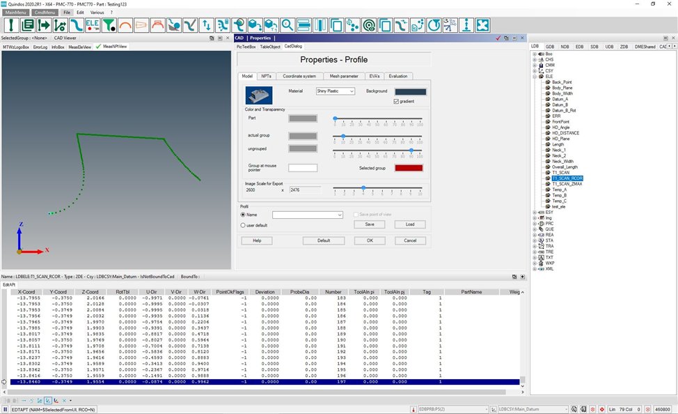
Hi Lee, your problem is you are trying to locate 2 "sharp" edges using a curve function. The point at the edges are thrown out of sequence, which is why you are struggling - you have 20 points in the raw data that describe a single point on the part (the sharp edge).
We can automatically remove the out of sequence points (see below), but you will loose the edge definition. Try the code below, maybe it helps.
I apologize for the delay. I fell ill after Thanksgiving, and am starting to finally get caught up with other quality responsibilities. I will definitely try this next week. Your patience is appreciated...
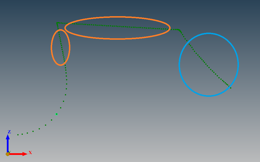
an alternative method.... use SLCPTS to pull points from the different sections and make specific geometries of them... for example pull the points circled orange into separate ELE's and build axes of them. Pull the points in the region circled blue and build a circle. Then intersect the two axes to get the point. Intersect the top axis and the circle to get the other point.
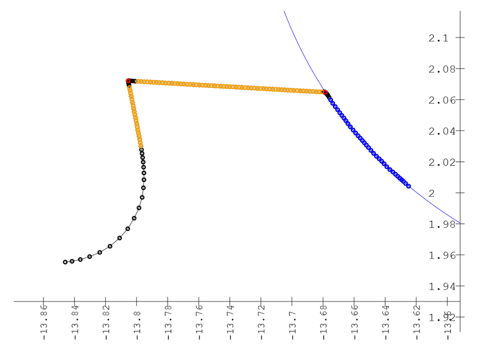
below code ... the two intersection points are red.
There is always more than one way to do something with Quindos..
Hi Lee, your problem is you are trying to locate 2 "sharp" edges using a curve function. The point at the edges are thrown out of sequence, which is why you are struggling - you have 20 points in the raw data that describe a single point on the part (the sharp edge).
We can automatically remove the out of sequence points (see below), but you will loose the edge definition. Try the code below, maybe it helps.
I ran this code, and get a distance of .0447 between the ZMax and ZXMax along the X axis. Measured with a caliper, the distance should be around .130. Hmmm...


 The highest Z value within the APT's of this scan is 2.1115. Using FXTREM, I'm getting 2.0846, which is the highest point at the very end of the scan. How can I get the highest Z and ZX values from an entire set of APT's?