I am trying to analyse a kinematically cross-linked double a-arm suspension. I have crated a template and made the standard parts following the conventions used in the fsae_2018 template. The 'gel_lower_control_arm' and 'gel_upright' are conventional.
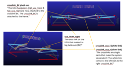
The 'gel_upper_control_arm' is now a big bell-crank that is attached to an additional part 'gel_crosslink_BC' which, in turn, is then attached to the frame through a mount: 'mtl_crosslink_BC_to_frame'. The bell-crank part of the gel_upper_control_arm is attached to a crosslink 'ges_crosslink_uca_l', which ties in to the 'ger_crosslink_BC' and vice versa. (I've attached a picture to help visualise).
These crosslinks make the system 'dependent' and essentially make a double a-arm setup behave like a beam (with regards to camber). With the above in mind I have a few questions.
- Does A/Car care if links pass through each other or will it just solve the system 'mathematically'?
- My assembly loads, but will not statically solve when attempting to simulate OWT or PWT within the 25 MAXIT. Could this be related to Q1?
- By making the system 'dependent' have I created an issue for the solver?
As is stands the symmetric parts are lca, uca, crosslink, upright, pushrods, dampers, springs and pushrod bellcrank. The single parts are the crosslinks. The crosslinks are attached using single spherical joints, everything else uses symmetric bushinsg and joints.
My mounts are:
lca_to_frame
crosslink_BC_to_frame
BC_to_frame (pushrod suspension)
damper_to_frame
tierod_to_steering
Hopefully the above makes some sense.
Woz
Attached Files (1)