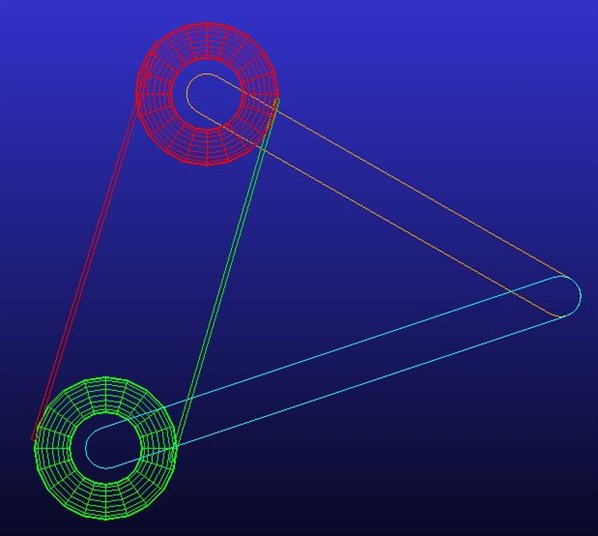
Say I have two arms with a revolute joint in between them. At the end of two arms are two pulleys which has a belt.
Is it possible to create a tangent action and reaction force at each pulley (no slip) so that there is no need to create belt/chain and all complex calculations that come with it. Can it be modeled without using ADAMS machinery?
@Henrik Skovbjerg being very new to ADAMS, I am still confused about using coupler to achieve what I want. Forgive me if I have missed this or made a wrong model, but I couldn't find a way to see / measure the tangent force. It seems coupler is a simple "if x rotates at A rpm, y rotates at B rpm with no action and reaction of forces caused by A on B".
But what I want to see is a tension force and its effect. Think of a simple pulley on edges of two links connected by revolute joint. When pulley A is rotated, it rotates the rope/belt and also rotates B. During this, the two pulleys come closer to each other due to tension force on rope/belt. I just want to model a simple one with no slip condition but couldn't understand how to begin.
rough sketch of belt on two pulleys on links connected by revolute joint.
Yes, the coupler will not provide the belt forces for you.
I, and several others, have done similar things, but it most likely will require a subroutine of you. And the build is not simple either. Lot's of complicated jprims involved.
You will need four dummy parts. One at each end of the free span of the belt. So now you have four parts, lets call them A_up, A_down, B_up, B_down. I will only describe how to constrain the 'up' parts and the markers you need.
Create a marker on the dummy part A_up at the tangent point of the upper belt run. Call it A_to_B. In the same way, create a marker on B_up at the tangent point of the free run at wheel B. Call it B_to_A
For A_to_B, use a orientation_in_plane function and point the Z-axis to B_to_A, and the Z_axis to A_center. Do the same thing for B_to_A, but point the Z_axis to A_to_B and x_axis to B_center. So the functions should be:
ORI_IN_PLANE(A_to_B,B_to_A,A_center,"Z_ZX") and corresponding for the B_to_A marker. A_cneter and B_Center of course belongs to the pulleys A and B.
It does help if you created the A_center marker with an ORI_IN_PLANE(A_center,B_center,Common_scissor,"Z_ZX") and then use that marker to position A_to_B at LOC_RELATIVE_TO(0,0,-A_radius,A_center), but this only helps if the radius of A and B are the same, more complicated otherwise.
That was only the creation of the markers. Now you need to lock it up for the solver.
Now create a inline jprim using the i_marker=B_to_A and j_marker=A_to_B and another inline jprim with the markers reversed. This forces the A_to_B to always be positioned along the z-axis of the B_to_A and the B_to_A will in the same way be located along the Z-axis of A_to_B. In other words, they are pointing towards each other.
Are you confused enough, or do you want me to continue? This was the easy first steps. If you are a beginner in ADAMS, this might be a bit overwhelming.
> For A_to_B, use a orientation_in_plane function and point the Z-axis to B_to_A,and the Z_axis to A_center. Do the same thing for B_to_A, but point the Z_axis to A_to_B and x_axis to B_center. So the functions should be:
You mean x right?
> Now you need to lock it up for the solver.
Bit not sure what to do here.
> Now create a inline jprim using the i_marker=B_to_A and j_marker=A_to_B and another inline jprim with the markers reversed. This forces the A_to_B to always be positioned along the z-axis of the B_to_A and the B_to_A will in the same way be located along the Z-axis of A_to_B. In other words, they are pointing towards each other.
I did create a jprim but it creates its own new i and j markers which are facing in Y direction rather than A_to_B and B_to_A.
Sorry for super late reply. The model that you linked works but I am super confused on how the model was created and have lots of questions. I have done few basic tutorials as I am just starting out but the things done here (looking at the code) made me puzzle. I am working on ADAMs/view.
Feel free to answer only those you want to though all answers would be great
How does one create part with just markers and attach a outline in ADAMS/view ?
In the code, i and j marker was directly assigned for joints. But when I try to create a joint, I don't see option to select for i and j marker.
Both the pulleys must rotate when the rope is pulled. And the lower pulley also must move upwards. So there are two possibilities:
The marker is fixed relative to the center of the pulley. It helps explain that when lower pulley center moves up, the marker also moves with it. But it doesn't explain how the contact point keeps on changing to maintain tangent.
The marker is fixed to the pulley. But it doesn't explain how it doesn't rotate when pulley rotates. Can it be because pulley never rotates in code but just small circles do for visualization?
It's that I am just starting out and bit overwhelmed to see the output yet not understand how it was created.
Basically you can imagine A/view as a graphical front end that collects your input and then creates commands to sent to the "kernel".
Unfortunately the joint creation dialogue in A/View usually creates new markes instead of using existing ones.
Check out the .cmd file. That's the necessary commands.
You can pack portions of it into a separate .cmd and read it with F2 to see what happens.
If you click something in the GUI, you'll find that command running trough the command window (press F3) or in the aview.log file that's in your working directory.
The answers on how to create parts, markers, joints and outlines is in that code.
Spend a few days on try&error with that methods and you'll gain a better understanding on what happens behind the curtains in A/View.
Concerning #3: Haven't got exactly in mind how it worked, but as far as I remember that "contact point" didn't "stay at the tangent point", but wandered along the tangent.
But that didn't matter in my case as I only needed the right torque and reaction force a the roll center bearing.
Ok thanks a lot for clearing up my confusions. I have looked into code and is a bit overwhelming at first. But within few days, I think I will understand enough of it to understand and create my own model. Thanks a lot again.