hexagon logo

Geometry errors for analysis model

does anybody have difficulty to build analysis model? 
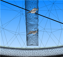
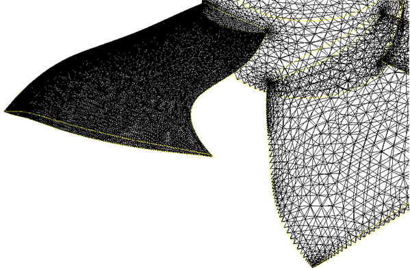
I've tried to make simulation with different fans blades, however, it happened very often to me that even simple shape geometries have edges/faces interferences.
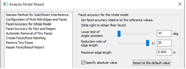
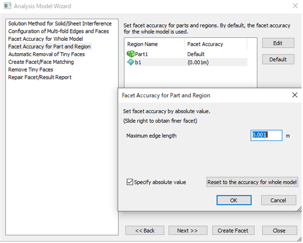
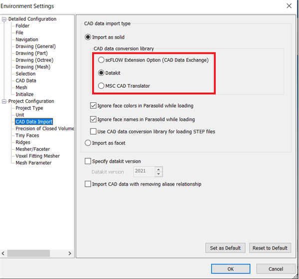
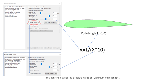
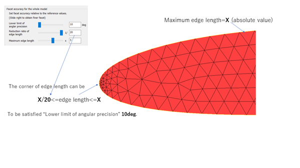
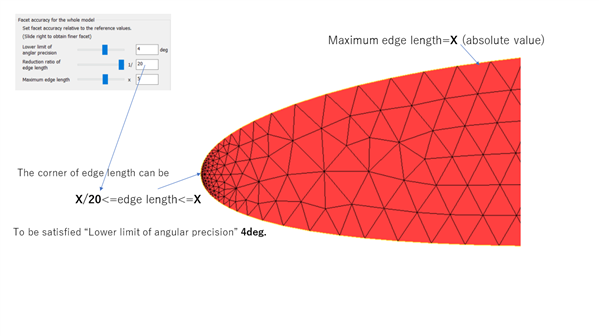
When I tried to adjust maximum length or for faceter parameters, it gets much slower and still couldn not build the analysis model.
 
Does someone have good tips for building model?
 

Attached Files (1)
  • In order to avoid the generation of interference surfaces, the basic idea is to increase the facet accuracy and divide the model into detailed facets.
    However, increasing the accuracy for the entire model will increase the computation time.
    In particular, detailed faceting is necessary to represent the R of the blade.
    In order to specify the faceting accuracy for a specific face region, we register the face region before building the model.
     
    The following is an example.
    First of all, the following settings are required for this purpose.
    fig1
    The next image shows an example of registering the face region of a specific blade as b1.
    fig2
    Except for the face area b1, the rest of the blades will be divided into 5 mm facets.
    fig3
    The face area b1 will be divided into 1mm facets.
    fig4
    The following is the result.
    The face area b1 was divided into 1 mm facets, and the other facets were divided into 5 mm facets.
    fig5
    Please give it a try.
    I wish you good luck.
  • thank you for your detailed instruction, it helped a lot!
    An additional question concerning geometry.
    Sometimes the geometries couldn't be import correctly, no matter 3dm files or step files from Rhinoceros.
    (Surface gap, interferrece or solid body doesn't close in the scFLOW)
    Should I adjust tolerance in scFLOW or Rhinoceros in order to increase accuracy, or any tip?
     
    Thank you in advance.
  • scFLOW has three different CAD data conversion libraries.
    The default is Datakit, which can convert 3dm formats.
    CAD_conv
    Each one have its advantages and disadvantages,
     but in any case, it often happens that the conversion is not perfect.
    One solution is to change the conversion library, but I don't know if that will solve the problem.
     
    Depending on the data, you may be able to solve the problem by using scFLOW's part editing function, or you may be able to use the wrapping function.
     In any case, it depends on the data and you have to deal with it individually.
     
    The best way to import CAD data is to use a CAD system that uses a parasolid kernel.
    NX, UG, SolidWorks, TOPsolid, SolidEdge, etc.
    Because scFLOW also uses the parasolid kernel.
  • Hello, mr. Hsun, if it is not bothering you, I would like to ask mr. Chuel about something too in edge/faceting option if you please.
    Mr. Chuel, how can i determine the "maximum edge length" of a cad part? Is this something done automatically? Or are there basis where i choose such length? Also, regarding the "Lower limit of angular precision", do i need to decrease this value from 10 to 0.5 when i deal with edges that have curvature? since i don't know how to make the best use of it.
    Thanks in advance.
  • Hello there.
    If you can understand the way to determine the maximum edge length as absolute value in scFLOWpre, you will be able to build appropriate analysis model.
    I will show it on the followings for you.
    slide1
    slide2
    slide3
     There is a more detailed description on "Solid-based Facetter" of User's Guid Preprocessor Reference, so it is also recommended that you check it. 
  • thanks for the contribution from everyone here.
    Another extended question:
    When I have multiple parts in the simulation and some parts require higher facet accuracy (such as airfoil/fan blade as above), the duration time for converting analysis model takes forever, didn't finish within 8 hours.
    If lower the facet settings are applied, the fan blade front (leading edge) looks sags and crests, which leads the pressure distribution on the blade become unsmoothly as well.
    Is there any advice for this configuration in terms of CAD, analysis model build or other solution?
    ​appreciated any experience/opinion.
  • Why don't you try to use Parasolid faceter instead of Solid-based one.
    Parasolid faceter will refine the facets to match the curvature.
    Parasolid_faceter
  • thank you for the reply.
    I've used Parasolid faceter for single-part case; however, when there's multi-parts in the simulation, Parasolid faceter also give me more unsolved errors and interferences which lead the analysis model fail.
    The only thing I could try is to modify my geometries in order to apply the parasolid faceter ?
  • I see.
    I guess that your multiple parts(solid data) may contains some problems with Analysis Model building, such as tangential contacts and self-interference.
    In order to identify what specific problems it has and what repairs are needed for the model, we need to check your multiple parts(solid data) itself.
    Regardless of which faceter is used, these solid data repairing are valid for successful Analysis Model building.
     
    You can learn about reparing of solid data  in "Preprocessing Examples" - "Objective 2 Modifying Problematic Solid Data"  of "Exerxice" manual .
    In spite of these trying , if you still could not solve the problems. I recommend you to have the formal MSC technical support . They can check your multiple parts and will find what repairing it needs.