hexagon logo

Reference CID and Analysis CID

Dear all,
I am trying to understand an example model with a bearing.
The two nodes which are used to constrain the bearing give for the Node Location Information:
Reference CID = Global Rectangular
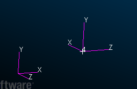
Analysis CID = 4 Rectangular
 
All other nodes are referring also to Global Rectangular CID for the Analysis CID.
I would like to know what this means 4 Rectangular?
The RBE2s which are connected to these points have no reference to other CID so I assume they take the global CID.
 
In the BDF-file there are some CORD2R defined:
CORD2R* 4                              0.             0.
*       0.            1.              0.            0.
*      0.              0.            -1.
*
CORD2R* 5                              0.             0.
*       0.            -1.             0.            0.
*      0.              0.            1.
*
CORD2R* 6                              0.             0.
*       0.            1.              0.            0.
*      0.              0.            -1.
*
CORD2R* 7                              0.             0.
*       0.            -1.             0.            0.
*      0.              0.            1.
*
CORD2R* 12                            -160.81759643554368.5
*      -226.72961425781-160.81759643554691.1295443819 -556.83722631104
*      -168.57967172422698.56095064975695.8543142001753
 
I don`t see a special CID.
Can you explain the 4 Rectangular?
Thanks


Parents
  • The reference CID defines the physical position of the node. The analysis coordinate system defines the directions of the degrees of freedom of that node, and thus the directions in which the node results are output. Your CID 4 has a different orientation than CID 0:
    ScreenShot2147
    This means that, for example, a Z displacement reported for that node would be an X displacement in global (CID 0).
     
    The analysis CID is also commonly used to define the directions of constraints applied to a node: so a constraint in X on that node would act in a different direction than a constraint in X on a node with CID 0 as its analysis CID.
     
    There is some useful discussion this topic in the Nastran Linear Static Analysis User's Guide, Chapter 3.
Reply
  • The reference CID defines the physical position of the node. The analysis coordinate system defines the directions of the degrees of freedom of that node, and thus the directions in which the node results are output. Your CID 4 has a different orientation than CID 0:
    ScreenShot2147
    This means that, for example, a Z displacement reported for that node would be an X displacement in global (CID 0).
     
    The analysis CID is also commonly used to define the directions of constraints applied to a node: so a constraint in X on that node would act in a different direction than a constraint in X on a node with CID 0 as its analysis CID.
     
    There is some useful discussion this topic in the Nastran Linear Static Analysis User's Guide, Chapter 3.
Children
No Data