hexagon logo

Drawing help (Again)

I have been asked to take a look at a drawing to see if I understand them. They look pretty simple but there is one thing which is giving me a bit of trouble.


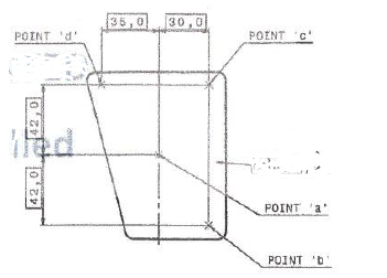
A this point I am only guessing that I would have to align to the points 'a', 'b', 'c' & 'd'. Usually in this situation I would have X,Y&Z data for these points if that was to be the case and it would be made obvious what they are for.

I will only show this of the part as it doesn't show anything really, but 'a' is a mid point between two opposing holes on the other side of the part and the rest seem to be constructed from this midpoint with reference dimensions. Has anyone seen this style of print before? is this a legitimate way of creating the datum system?
Parents
  • Points ' b ' 'c ' and 'd ' are target points as I see it and point ' a ' is used to position the target points. There should be a note on the drawing as to what the points are used for and how they relate to the datum setup of the part. The target zone should be stated and may be in the general workmanship/drafting standards of the customer.
Reply
  • Points ' b ' 'c ' and 'd ' are target points as I see it and point ' a ' is used to position the target points. There should be a note on the drawing as to what the points are used for and how they relate to the datum setup of the part. The target zone should be stated and may be in the general workmanship/drafting standards of the customer.
Children