hexagon logo

Plane, Circle, Width Alignment ???

I have gained so much over the years from the contributors of this forum. Thank y'all for sharing your wisdom, knowledge, and experiences!

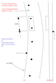
With that said, I would like your opinions on the attached crude drawing. It's third angle projection and in accordance with ASME Y14.5M-1994. The material at it's thickest point is 1 1/4". The total length of the part is 60". Here are the questionsRelaxed

1. How would you align this part for the position and profile call-outs back to ABC?
2. Since B is a huge diameter and C is a width, what would you use to rotate to?
3. PC-DMIS can't solve a constructed line from a circle/cylinder (B) to a width/mid-line/mid-plane (C). So what would you use instead to comply with the standard and satisfy the software?

There's some dissension here with regard to designer intent as well as compliance to the standard.

Thank y'all again for taking the time to share!!!

Attached Files
Parents
  • As a radius, B has a center point. Clocking then is from B (center point) to C (the midplane/line/point of the feature of size C).
  • I've been using the small arc method for years and understand all of the principles/techniques for creating sound alignments that lock down all 6 DOF. I guess my major question is about design intent? If you were to make a check fixture for this part, how would the position of the holes relate to a center point 14 feet away? Yes, datum C is stopping the rotation by fitting into a slot. So to create this line from B to C, what would you use? (opposing points to create primary (tangent) planes and then construct a mid-plane, just 2 opposing points to create a mid-point, a mid-line that pierces datum B, etc.)

    I was hoping to gain some opinions on accurate, repeatable, compliant measurements for the stated datum scheme and associated call-outs.
Reply
  • I've been using the small arc method for years and understand all of the principles/techniques for creating sound alignments that lock down all 6 DOF. I guess my major question is about design intent? If you were to make a check fixture for this part, how would the position of the holes relate to a center point 14 feet away? Yes, datum C is stopping the rotation by fitting into a slot. So to create this line from B to C, what would you use? (opposing points to create primary (tangent) planes and then construct a mid-plane, just 2 opposing points to create a mid-point, a mid-line that pierces datum B, etc.)

    I was hoping to gain some opinions on accurate, repeatable, compliant measurements for the stated datum scheme and associated call-outs.
Children
No Data