hexagon logo

Concentricity problem.

Hello everyone.

Recently i'm having a huge problem with one of my customers.
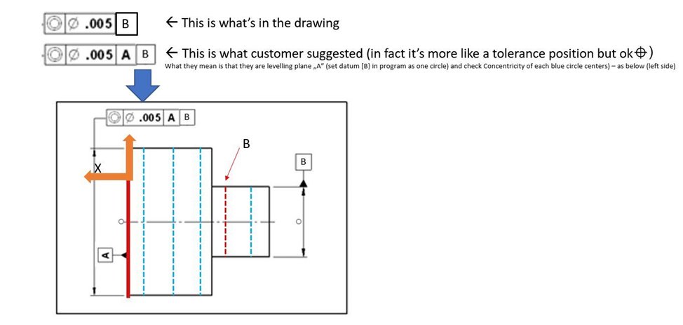
One of our parts have drawing with a concentricity characteristic for two holes [one of them is a datum].
We produce the parts, measure'em [results are always ok] and deliver to our customer - then they claim the concentricity is out of tolerance.

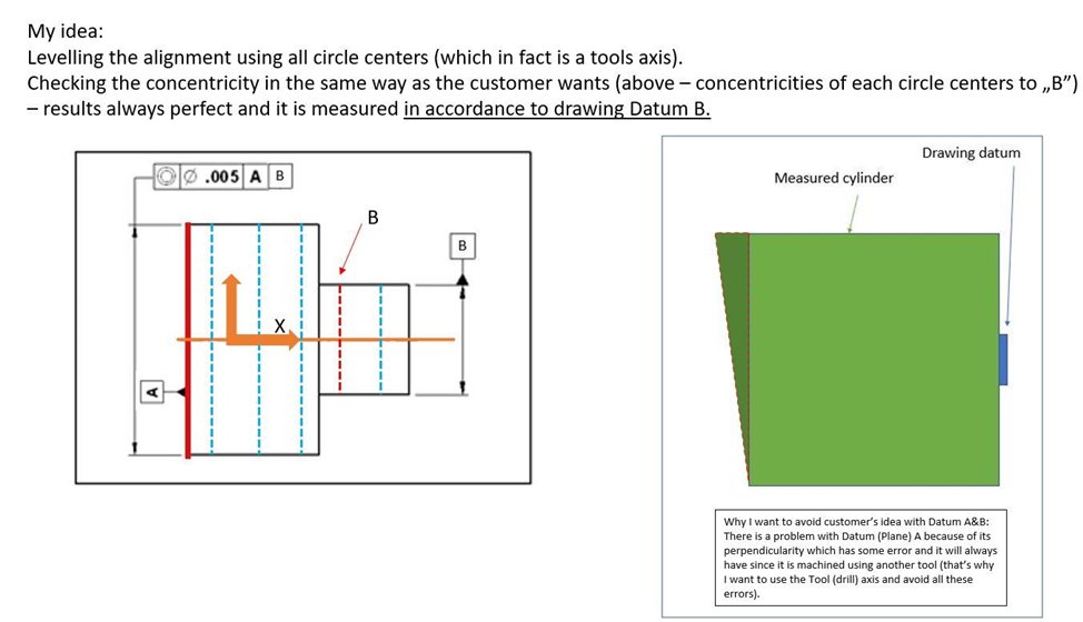
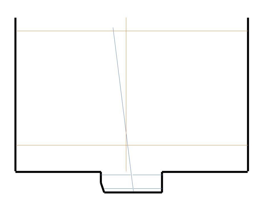
Now i need to explain the issue a bit - both holes are drilled on CNC using just one form tool at once so i'm not afraid about the result [it'll be always ok - i'm sure about that]. But the problem is that the datum is very small and short [about 2mm depth] and measured cylinder is very long and has a large diameter [check the attached image on the right side]. When i checked the repeatability on one part about 80percent of results were similar and 20perc. different about 0.02mm [our customer has some crappy CMM so their results vary from 0.01mm up to even 1.6mm - which is physically not possible Rolling eyes]. That's why we changed internally the datum. Currently our CMM checks both methods - 1. short/small diameter as datum [as in drawing]; 2. long diameter as a datum. In case the 'correct' method is out of tolerance we remeasure it and then it's ok Slight smile

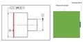
So, the customer wants to use the drawing datum anyway. And they asked to measure it by adding a surface plane as another datum [attached picture on the left side. The mentioned plane with red color].
And now I don't understand what exactly they want, what does the datum mean - since we check one axis to the another - what does the plane surface mean/Astonished
Can't just ask them [asians - language barrier, they can't speak english].

What would you guys do now/ I need a support from experienced metrologist-negotiators.

Sorry for a crappy sketch - i'm working on a touchpad + powerpoint. This is not the sketch i got from the customer - it's a random pic from the internet but basically it's the same.

thx

Attached Files
  • What they probably mean is Position to A & B. Level to A and set origin to B. Then check the position of the hole. Is it possible to ask them to change it from concentricity to position?
  • What they probably mean is Position to A & B. Level to A and set origin to B. Then check the position of the hole. Is it possible to ask them to change it from concentricity to position?


    I tought exactly the same but this will not solve the problem. Repeatability problem comes from the "short" axis distortion - any small CMM error there etc. causes large deviation of the concentricity later on. So they will stil have not repeatable results (not real in some cases).

    And funny thing is that that's why we have all the GD&T stadards,etc. for that there shouldn't be any "what the designer probably mean is" Wink
    But this can't be fixed... I'm just complaining... Slight smile
  • As said, that's the plane will ensure the repeatability, B is only the origin, not orientaion.
    Maybe the most problem is the Ø0.005 tolerance...
    And the tip changing... If you measure A and B with a 1 mm tip, you can't measure the large cylinder with it, without shanking...
  • How is customer measuring the part for concentricity? replicating methods is best, CMM does not calculate concentricity properly. "So, the customer wants to use the drawing datum anyway."--That is why it is drawn that way, you can inspect internally any way you want but ultimate correct interpretation to drawing must be the end game unless an agreeable solution alternately is made and get this in writing as you are deviating from drawing. I have many conversations with "I am machining it this way and inspecting this this way CMM is failing my part, I don not understand"-- my reply let's inspect to the drawing now, find now the error is the same. A small surface of a datum always creates potential issues and that axis/location is extended a small amount of error calculates out as it extends over length of feature. Form error and minutia matter. as explained in post 2 ID's and are drilled, drills walk. Long drills walk more than a short drill and drills are not made for precision. A rigid boring bar may yield better results but you also need everything perfect. Boring bars may also deflect but if there is any taper in machine setup/axis this could be an issue in what was described also.
  • I would explain to the customer that it can't be a concentricity (ISO1101 definition) because circles are not coplanar.
    It can't be a coaxiality, because the datum is too short.
    So it could be dimensionned as a position...
  • The planar datum helps eliminate the projection error


  • the plane will ensure the repeatability,

    The planar datum helps eliminate the projection error


    You are guys right, but there is another problem with this plane that I will show you below.


    I would explain to the customer


    It's easy to say. They don't care about anything but what's on the drawing - they literally want to have everything exactly according to drawing no matter if it's correct or not, problematic, etc. (But of course I really understand them because they base on their experience and know-how. I'm not saying it's wrong or something).
    Right now I have an idea to fulfill their requirements, I'll show it down below.

    Yes, You are absolutely right. I just want to eliminate all the errors that affect the final result - the errors that the customer doesn't think about and doesn't take into consideration.

    OK, so in the attachments there is:
    - one image that shows the drawing's requirements + customers suggestion of their additional measuring method.


    - second image is a measuring method suggested by me + explanation what makes a problem with a measurement using customer's method.


    What do you guys think about my meas. method suggestion? I must add that my method also guarantees good repeatability.

    Thanks in advance!

    <I hope everything's clear for you, I didn't want to make any confusion with my low powerpoint skills - sorry for that Wink>
    <Anyway thank you all for support and every good idea>
  • Your method is not measuring in accordance with the drawing you are making an average centre axis by using both diameter. Why not use the shoulder face of datum B was this not machined at in the same operation as Diameter B, doing this would give a better representation of the concentricity.
  • Datum A should have some kind of tolerance controlling the form as well. If it hasn't, bad design. If it has, are you within that tolerance?

    What prevents you from measuring these as coaxiality? It seems that is what the customer is wanting, looking at the DRF (B only).
  • Datum A should have some kind of tolerance controlling the form as well. If it hasn't, bad design.


    - well, it doesn't. Problem is that the any (allowable) shape errors of the smaller diameter cause deviation of it's axis end final result out of the tolerance.


    Simple sketch here, but everything is more complex than it looks (at least for me, that's why I asked here).