hexagon logo

Virtual Condition Vs MMC Check Fixture

So I have a part here that has a nominal diameter of 17.169 +/- .01. It also had a perpendicularity callout of .01 at MMC to A (Plane on the bottom of the part)

We sent the print to a gage supplier and they created the gage at Virtual condition. So essentially the Datum B locations are 17.149.( -0.01 for MMC and -0.01 for Perpendicularity) I understand how Virtual condition works and the concept behind it I believe but shouldn't the gage be made at 17.159 since that is the smallest diameter allowed? If the Datum B surface slants towards the smallest diameter the farthest point that it could slant would be a diameter of 17.159 right?

I understand Datum A plays a role in the additional tolerance but I can't seem to wrap my head around they why. Could anybody help me understand it?

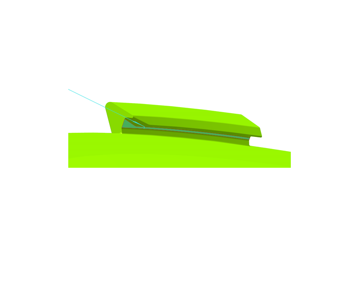
This is a CMM check fixture. Datum A is 8 net pads around the bottom surface of a ring for Z. Datum B is 3 Blades that the part is rotated onto to control the XY. Attached is a picture of Datum B. Datum A is the underside of the Flat you see below the Blade rotation slot.


Parents
  • It is impossible in most cases to build a single gage that will check everything. In this case your gage to check the GD&T is incapable of also simultaneously checking the size of the hole.

    If you want to know more about the logic and rules behind gage design I recommend ASME Y14.43 Dimensioning and Tolerancing Principles for Gages and Fixtures.

    HTH & ymmv

    Sunglasses
Reply
  • It is impossible in most cases to build a single gage that will check everything. In this case your gage to check the GD&T is incapable of also simultaneously checking the size of the hole.

    If you want to know more about the logic and rules behind gage design I recommend ASME Y14.43 Dimensioning and Tolerancing Principles for Gages and Fixtures.

    HTH & ymmv

    Sunglasses
Children
No Data