hexagon logo

Datum Precedence

Hi all,

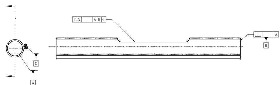
Today's conversation is datum precedence.

Should this be A|C|B and can it be A|B|C? (according to asme y14.5)

My understanding is that it SHOULD be A|C|B and that A|B|C is wrong - but it has now turned into a topic of debate as it cannot be found in the standard.
Parents
  • PER GD&T ASME Y 14.5 2009 Paragraph 4.10
    (if you google for a pdf you can generally find a copy for free)
    4.10.1 Development of a Datum Reference Frame for
    Parts With Planar Surface Datum Features
    The feature control frame in Fig. 4-2 illustrates the
    datum reference frame for the part shown in its functional
    assembly in Fig. 4-2, illustration (b). Figure 4-2
    illustrates the development of the datum reference
    frame along with degrees of freedom. The datum features
    referenced in the feature control frame immobilize
    the part and constrain the six degrees of freedom (three
    translations and three rotations) to establish a datum
    reference frame. Relating a part to a datum feature
    simulator and a datum reference frame in this manner
    ensures consistent understanding of engineering
    requirements. See Fig. 4-1.

    (a) In Fig. 4-2, illustration (a), datum feature D is
    specified as the primary datum feature. Where a surface
    is specified as a datum feature, the high point(s) on the
    surface establish a datum plane. This primary datum
    feature contacts the datum feature simulator on a minimum
    of three points
    (see para. 4.11.2 for discussion on
    rocking or unstable datum features). In this example,
    where the primary datum feature contacts the datum
    feature simulator, three degrees of freedom (one translation
    and two rotations) are constrained: rotation about
    the X-axis (u), rotation about the Y-axis (v), and translation
    in the Z direction.

    (b) Datum feature E is specified as the secondary datum
    feature. This feature contacts the datum feature simulator
    at a minimum of two points. See Fig. 4-2, illustration (d).
    In this example, where the secondary datum feature contacts
    its datum feature simulator, two degrees of freedom
    (one translation and one rotation) are constrained: translation
    in the X direction and rotation about the Z-axis (w).

    (c) Datum feature F is specified as the tertiary datum
    feature. See Fig. 4-2, illustration (e). In this example,
    where the tertiary datum feature contacts its datum feature
    simulator at a minimum of one point, the remaining
    degree of freedom
    is constrained: translation in the
    Y direction.

    4.10.2 - 4.10.4 goes into more detail when cylinders are involved as datums, and how constraining should be conducted.

    The order of the datums should always control the most axii of freedom from most to last, in the specified order, as what said. -CAN MAY MUST-

    Another typical method , and in paraphrasing the bold portions of the GD&T Spec above, is by control via planar points of contact 3, 2, 1.
    -Three points equal a level plane, controlling three degrees of freedom,
    -Two points equal a line about the plane, and controls two degrees of freedom,
    -And one point to control the translation of the remaining axis of freedom.

    PCDMIS corraborates this during their training. All alignments within PCDMIS should be conducted by assigning LEVEL, ROTATE, and ORIGIN (Translate).
Reply
  • PER GD&T ASME Y 14.5 2009 Paragraph 4.10
    (if you google for a pdf you can generally find a copy for free)
    4.10.1 Development of a Datum Reference Frame for
    Parts With Planar Surface Datum Features
    The feature control frame in Fig. 4-2 illustrates the
    datum reference frame for the part shown in its functional
    assembly in Fig. 4-2, illustration (b). Figure 4-2
    illustrates the development of the datum reference
    frame along with degrees of freedom. The datum features
    referenced in the feature control frame immobilize
    the part and constrain the six degrees of freedom (three
    translations and three rotations) to establish a datum
    reference frame. Relating a part to a datum feature
    simulator and a datum reference frame in this manner
    ensures consistent understanding of engineering
    requirements. See Fig. 4-1.

    (a) In Fig. 4-2, illustration (a), datum feature D is
    specified as the primary datum feature. Where a surface
    is specified as a datum feature, the high point(s) on the
    surface establish a datum plane. This primary datum
    feature contacts the datum feature simulator on a minimum
    of three points
    (see para. 4.11.2 for discussion on
    rocking or unstable datum features). In this example,
    where the primary datum feature contacts the datum
    feature simulator, three degrees of freedom (one translation
    and two rotations) are constrained: rotation about
    the X-axis (u), rotation about the Y-axis (v), and translation
    in the Z direction.

    (b) Datum feature E is specified as the secondary datum
    feature. This feature contacts the datum feature simulator
    at a minimum of two points. See Fig. 4-2, illustration (d).
    In this example, where the secondary datum feature contacts
    its datum feature simulator, two degrees of freedom
    (one translation and one rotation) are constrained: translation
    in the X direction and rotation about the Z-axis (w).

    (c) Datum feature F is specified as the tertiary datum
    feature. See Fig. 4-2, illustration (e). In this example,
    where the tertiary datum feature contacts its datum feature
    simulator at a minimum of one point, the remaining
    degree of freedom
    is constrained: translation in the
    Y direction.

    4.10.2 - 4.10.4 goes into more detail when cylinders are involved as datums, and how constraining should be conducted.

    The order of the datums should always control the most axii of freedom from most to last, in the specified order, as what said. -CAN MAY MUST-

    Another typical method , and in paraphrasing the bold portions of the GD&T Spec above, is by control via planar points of contact 3, 2, 1.
    -Three points equal a level plane, controlling three degrees of freedom,
    -Two points equal a line about the plane, and controls two degrees of freedom,
    -And one point to control the translation of the remaining axis of freedom.

    PCDMIS corraborates this during their training. All alignments within PCDMIS should be conducted by assigning LEVEL, ROTATE, and ORIGIN (Translate).
Children