I'm discussing a miscorrelation with a supplier and wanted to be clear on the CMM report out for a profile of a line. On the CMM dimensional report;
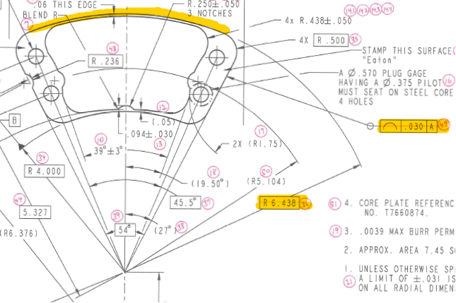
Do I select the R 6.438 dimension and report it out as a nominal with a +/- 0.015?
OR
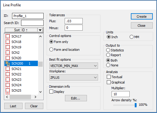
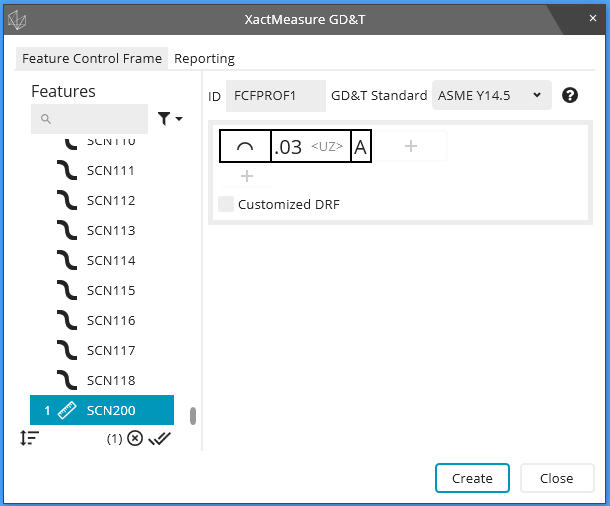
Do I select the Profile of a line and select the R 6.438 feature and report it out as a profile of a line with a +/ 0.015?
I understand a basic number does not have a tolerance and the control fame is the tolerance. I just want to be clear on how to report it out from PC-Dmis. thanks for your time!
Attached Files