hexagon logo

Scan results different from keyed-in points

I have a part with a very tight profile tolerance (form+location) of .0005. I wrote a program with a model and aligned to all 3 datums.

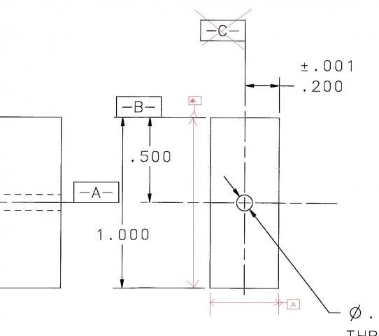
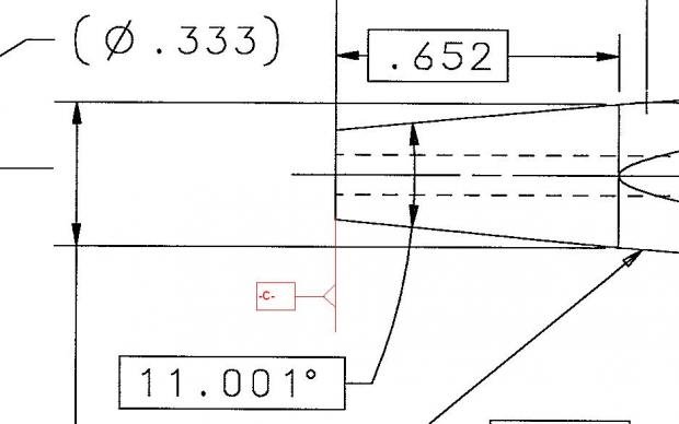
I keyed in gage points and read the vectors from the model. Part is out of tolerance (which I expected) by about .001, the profile being off center.

Next I added a linear TTP scan along the same section where I probed the gage points. The scan shows deviations up to .018!Confused Same program, same part, same alignment.

What could I be doing wrong with my scan to get a result that differs so much from my keyed-in points?
Parents
  • To be honest I dont understand what you mean by the .400 faces. From the looks of it -A- is a cylindrical feature, yet you are Leveling to the Face? If thats the case, why are you creating a mid plane? Unless the engineer changed the datums completely. The print is not very good, but it seems that -A- is (Ø.093) is the center of the part, -B- is the OD ( Also a center of the part), -C- is the right face. So I would place the part so that the front is the tapered Ø, Level to either -A- or -B- depending on the function, and -C- for the Y zero.


    I agree that the print is bad. I have had the datums changed by engineering, and I will try and clarify that. First, a little more detail about the part...

    This part is an electrode for EDM. The rectangular side on the right is where the electrode loads into the toolholder. The center hole is for flushing, and has no effect on the geometry of the part being manufactured. The intent of the engineer was to control the profile from centerline to make it symetrical; that way the electrode could be loaded either side up and still make a good part.

    The outcome is that datum -A- was clarified: it was not intended to be the center hole, but the center plane (yes, it was poorly drawn) parallel to the long edge of the rectangle (right-hand view, 1.000 dim). The attached pic shows the change. The .400 face to which I was referring is the shorter edge in the same view. Datum -C- must be the face on the left end because all of the gage points are dimensioned from it.

    So, when looking at my actuals for the GP you asked about earlier, I would expect to see <0.1666,0,-.652>, since the X and Y origins are on C/L and Z origin is on the left face. The vector was read from the model. My guess is there is some infinitely small flat in the computed geometry of that section.


Reply
  • To be honest I dont understand what you mean by the .400 faces. From the looks of it -A- is a cylindrical feature, yet you are Leveling to the Face? If thats the case, why are you creating a mid plane? Unless the engineer changed the datums completely. The print is not very good, but it seems that -A- is (Ø.093) is the center of the part, -B- is the OD ( Also a center of the part), -C- is the right face. So I would place the part so that the front is the tapered Ø, Level to either -A- or -B- depending on the function, and -C- for the Y zero.


    I agree that the print is bad. I have had the datums changed by engineering, and I will try and clarify that. First, a little more detail about the part...

    This part is an electrode for EDM. The rectangular side on the right is where the electrode loads into the toolholder. The center hole is for flushing, and has no effect on the geometry of the part being manufactured. The intent of the engineer was to control the profile from centerline to make it symetrical; that way the electrode could be loaded either side up and still make a good part.

    The outcome is that datum -A- was clarified: it was not intended to be the center hole, but the center plane (yes, it was poorly drawn) parallel to the long edge of the rectangle (right-hand view, 1.000 dim). The attached pic shows the change. The .400 face to which I was referring is the shorter edge in the same view. Datum -C- must be the face on the left end because all of the gage points are dimensioned from it.

    So, when looking at my actuals for the GP you asked about earlier, I would expect to see <0.1666,0,-.652>, since the X and Y origins are on C/L and Z origin is on the left face. The vector was read from the model. My guess is there is some infinitely small flat in the computed geometry of that section.


Children
No Data