
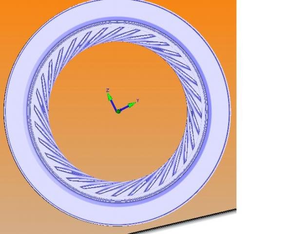
The picture shows a cross-section of the part, with flow paths exposed. I need to be able to probe all the way into those flow paths. Since the space in those passages is pretty tight (and so are the tolerances), I will need to make sure that the path I am checking is square to the machine's Z axis. We will then use the rotary table to index the part for each flow path.
Is there any way for me to ensure that my part model is square to the machine model? The opposite side of the part has a timing hole which I can use to locate the flow path, but I don't know how to orient the model so that hole is at a certain angle from Z+.
I tried tinkering a bit with Quick Fixture mode, but I haven't gotten far.


