hexagon logo

Saturday morning GD&T --- Surface profile of a diameter (cast cylinder)

Morning all,

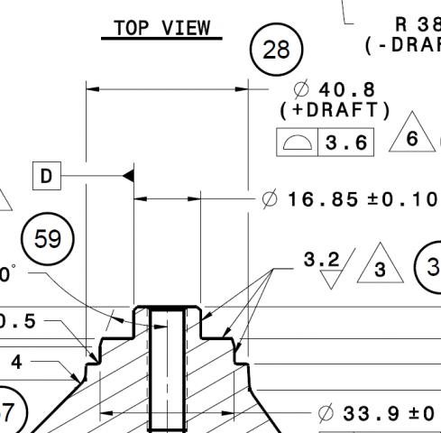
Saturday morning, New customer, and PPAP being setup to run for next week, and one GD & T callout that leaves me scratching my head! Confused

The attached drawing shows the 40.8 Ø (+ draft (3° per notes is draft)) on a cast OD with a profile of 3.6 and according to the control plans Engineering sent down on the inspection plans this is being called out to check as true position of 1.8 back to -D-.Astonished

I've never seen profile of a surface called out to an OD (especially a cast OD) so what am I looking at here? Reading the GD&T book this late in the morning (I'm third shift) is not helping. Near as I can figure out with the book I'm looking at checking this cast surface with a circle in two or three spots and just figuring out what the high and low spots would be trig'ing out the possible largest diameter. Or should I check with a line on the OD and figure/report where the tangent points on the line lay within the surface profile?

Any thoughts / suggestions?? I Just need to make sure that we are reporting this for the PPAP, and subsequently an annual dimensional report for the most part given that it is a cast feature, but I want to make sure that it is correct too. I'll be back in tonight to work on this so any help from you weekend warriors would be wonderful! Thanks!


Parents
  • It looks like the draft angle is included in the CAD/print. If that is the case, you could just build it as a cone, and report profile (form only) of the cone (that would also allow you to report the (included angle) of the cone to report the draft angle*2 (divisible with variables)). It seems to work fine with a cylinder. If not, take individual points, whatever is necessary to sufficiently represent the surface, create a set from those points, and then report profile of that.

    If draft is not in CAD, I don't know how that would actually be possible to represent with PC-DMIS.
Reply
  • It looks like the draft angle is included in the CAD/print. If that is the case, you could just build it as a cone, and report profile (form only) of the cone (that would also allow you to report the (included angle) of the cone to report the draft angle*2 (divisible with variables)). It seems to work fine with a cylinder. If not, take individual points, whatever is necessary to sufficiently represent the surface, create a set from those points, and then report profile of that.

    If draft is not in CAD, I don't know how that would actually be possible to represent with PC-DMIS.
Children
No Data