hexagon logo

Saturday morning GD&T --- Surface profile of a diameter (cast cylinder)

Morning all,

Saturday morning, New customer, and PPAP being setup to run for next week, and one GD & T callout that leaves me scratching my head! Confused

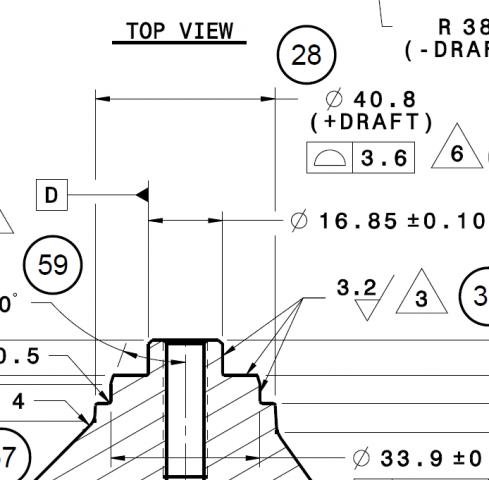
The attached drawing shows the 40.8 Ø (+ draft (3° per notes is draft)) on a cast OD with a profile of 3.6 and according to the control plans Engineering sent down on the inspection plans this is being called out to check as true position of 1.8 back to -D-.Astonished

I've never seen profile of a surface called out to an OD (especially a cast OD) so what am I looking at here? Reading the GD&T book this late in the morning (I'm third shift) is not helping. Near as I can figure out with the book I'm looking at checking this cast surface with a circle in two or three spots and just figuring out what the high and low spots would be trig'ing out the possible largest diameter. Or should I check with a line on the OD and figure/report where the tangent points on the line lay within the surface profile?

Any thoughts / suggestions?? I Just need to make sure that we are reporting this for the PPAP, and subsequently an annual dimensional report for the most part given that it is a cast feature, but I want to make sure that it is correct too. I'll be back in tonight to work on this so any help from you weekend warriors would be wonderful! Thanks!


Parents
  • The print says 40.8 +draft. So the diameter at the theoretical sharp corner at the top of the feature is 40.8 and it gets larger as you go down. I would measure a few hits on the top shoulder of the feature, use that as Z origin, and set X,Y origin to datum D axis. You could then measure the feature using the auto cone tool as Vinnie has mentioned. You will need to edit the hits on the lowest level because it appears that it extends further down on the right hand side of the print.

    Now you can dimension the cone using a legacy position dimension as instructed by the engineer (make sure you check perp to centerline so it doesn't try to give you 3D position.) I would label that dimension as reference only since it is not called for on the print (the engineer might have a really good reason for asking for this information so best to try to provide it.)

    Now I would also create a constructed set composed of the hits from the cone: Cone1.hits[1..numhits] or Cone1.Hit[1],Cone1.hit[2],Cone1.Hit[3],etc. (the second way is tedious but sometimes it helps avoid errors telling you that there aren't enough features for analysis)

    Use a legacy profile of surface- formonly dimension with plus tolerance of 3.6 to dimension the constructed set. Just to be sure that all of your hits are being considered by the dimension create an analysis view to verify that you can see all of the hits in the image. Whatever you see there is what is being processed in the dimension. You can delete the analysis view once you have verified that things are working properly.

    Now you will have satisfied both the print and the engineering request. I would then discuss with the engineer, as Roberto mentions, to understand the intent behind the request. Perhaps he doesn't understand GD&T and you can educate him on what surface profile is. Perhaps he knows something about the function of the part that is driving the request. In that case he can educate you on the parts function.
Reply
  • The print says 40.8 +draft. So the diameter at the theoretical sharp corner at the top of the feature is 40.8 and it gets larger as you go down. I would measure a few hits on the top shoulder of the feature, use that as Z origin, and set X,Y origin to datum D axis. You could then measure the feature using the auto cone tool as Vinnie has mentioned. You will need to edit the hits on the lowest level because it appears that it extends further down on the right hand side of the print.

    Now you can dimension the cone using a legacy position dimension as instructed by the engineer (make sure you check perp to centerline so it doesn't try to give you 3D position.) I would label that dimension as reference only since it is not called for on the print (the engineer might have a really good reason for asking for this information so best to try to provide it.)

    Now I would also create a constructed set composed of the hits from the cone: Cone1.hits[1..numhits] or Cone1.Hit[1],Cone1.hit[2],Cone1.Hit[3],etc. (the second way is tedious but sometimes it helps avoid errors telling you that there aren't enough features for analysis)

    Use a legacy profile of surface- formonly dimension with plus tolerance of 3.6 to dimension the constructed set. Just to be sure that all of your hits are being considered by the dimension create an analysis view to verify that you can see all of the hits in the image. Whatever you see there is what is being processed in the dimension. You can delete the analysis view once you have verified that things are working properly.

    Now you will have satisfied both the print and the engineering request. I would then discuss with the engineer, as Roberto mentions, to understand the intent behind the request. Perhaps he doesn't understand GD&T and you can educate him on what surface profile is. Perhaps he knows something about the function of the part that is driving the request. In that case he can educate you on the parts function.
Children
No Data