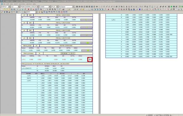
I am measuring this part right now this is a cylinder about 3 inches tall. The od is dat-b. The top plane is dat-a and dat-c is a slot in the center of the part. The part has 4 counter bore holes along the side of it every 90 degrees. Here is a picture of what the result looks like, and i know its wrong.
Do i need the od dat to be a cylinder or a circle?
Does it matter if its a constructed cyl or an auto cyl?
My dat c is a constructed width, should it be the line instead?
No name calling from me, just trying to understand your reasoning. I like to learn something new every day, so this is something new to me. I think if you do some digging, was it Josh Carpenter(sp?), posted an explanation of datum shifts and the Xact measure position output.
No name calling from me, just trying to understand your reasoning. I like to learn something new every day, so this is something new to me. I think if you do some digging, was it Josh Carpenter(sp?), posted an explanation of datum shifts and the Xact measure position output.
Xact may outperform legacy when it comes to Datums Shift, I don't know. If I write a program for internal parts, I stay clear of datum shift unless I really need it to use up all of my toll. If the part is good without any Datum shift, the part is GOOD. Simplify your life, not complicate is my Motto
I have to agree with WolfMan. I prefer legacy, partly for the same reason and partly for a different reason.
I like knowing exactly what is going on with my alignment, because I am directly telling PC-DMIS what to do, but also, Xact and Datum Definition doesn't work well with Datum targets. It's hard to make a primary "plane" when your points are not co-planar and have different vectors.
What technique are you using to rotate with the datum C slot?
You want to try this
Take multiple points along the slot length, top and bottom of slot.
Use those points with a best fit ROTATE ONLY method.
Then remeasure the slot for position and width.
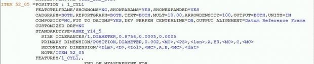
the actually call out is TP .002 |A|B|C|
Yeah there should be four, I just have the one in it so its easier to manage tell I figure out how to get the dimensioning correct. Does it matter about my alignment? Do I need to level to the OD cyl dat-b? or is leveling to the top plane dat-a the same?
What technique are you using to rotate with the datum C slot? You want to try this Take multiple points along the slot length, top and bottom of slot. Use those points with a best fit ROTATE ONLY method. Then remeasure the slot for position and width.
you cannot use a BF Rotate Only method, the callout is specifically to AB and C, C is being the slot, which mean the 90° must come from the Slot.
I was assuming that A and B were already aligned. Is this your argument?
Its not an argument, it a fact. If you do not have a -C- Slot, the you could do the BF rotate ONLY, but since you have a specific -C- that locks 2 DOF, you are not allowed to perform a BF any longer
So the following alignment technique is not allowed?
Keep in mind I have not seen the print I'm just curious about this method for clocking a slot on the described shaft.
Level and zero A surface.
Origin B
Use be best fit rotate only for C
Its not an argument, it a fact. If you do not have a -C- Slot, the you could do the BF rotate ONLY, but since you have a specific -C- that locks 2 DOF, you are not allowed to perform a BF any longer
He is saying to use BF rotate with the opposed elements for the rotation. It's slightly unorthodox, but not wrong. And C is likely not the "slot", rather it is more likely the median of opposed parallel elements. A TP of the 'slot' to A|B|C suggests this.
I am measuring this part right now this is a cylinder about 3 inches tall. The od is dat-b. The top plane is dat-a and dat-c is a slot in the center of the part. The part has 4 counter bore holes along the side of it every 90 degrees. Here is a picture of what the result looks like, and i know its wrong. Do i need the od dat to be a cylinder or a circle? Does it matter if its a constructed cyl or an auto cyl? My dat c is a constructed width, should it be the line instead?
I added two pictures if that helps
please help!!
I can only go by, by what the OP said. He said that Slot is -C-, which mean he cannot perform a BF. If he Rotates to a Slot, then does a BF rotate only, then the Rotation to a Slot is no longer Exist, it will re rotate it to Best Fit . Which is clearly not the FCF according to the OP.
Also if you only select -C- for the BF rotation, I am not sure it will rotate at all, since it needs at least one more feature to determine the BF.
Not 100% sure on the last part, still it is not allowed with having -C-