hexagon logo

Xactmeasure questions concerning Profile.

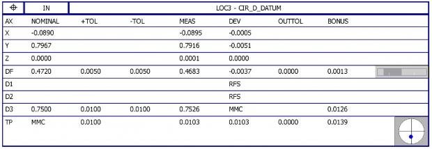
I have been tasked with explaining some items concerning a program I inherited concerning Xactmeasure Profile. I have a two part question. Attached is a pic of the profile dimension results and the D datum results. First, the call out is |Profile|0.010|A|D(M)|B|. A is a plane, D is an intersect of a cylinder and plane (constructed circle for size) and B is a line. The attached results show the D Datum size at 0.4683 and the nominal at 0.472. I am trying to figure out the Bonus of 0.0113. Is it the bonus of the feature plus it's position tolerance, see second attachment? I have looked over 2.8, 4.11.5, 4.16.2, 4.16.4 & 4.17 and now my head hurts. This one I am confused as the standard shows the other way around, Datum is profile and feature is position.Second, if datum A is zplus and B is in the X direction, why whould I have a Y shift? Please let me know if you need more info. My previous job only used legacy reporting and this one has a lot of parts utilizing this boundary condition.
  • Go to your the profile dimension and turn GRAPH=ON then MULT=100.
    this will show you where the hits you are taking are showing up on the CAD model.

    with a profile of .010 you have a +/-.005 on both sides of the imaginary "nominal" surface. if your max hit is -.0035 from nominal and your other MIN hit is .002 from nominal you have a total of .0055 profile but you never break out of your +/-.005 profile tolerance.

    in your case your max/min values are .0027. combined that gives you a total profile of around .0055

    BONUS tolerance is applied when you are figuring MMC/LMC.
    http://www.toolingandproduction.com/qim/0205bonus_tolerances.aspx

    since your D3 feature is MMC, nominal is .750 +/-.010 and the feature measure .7526 (a difference of .0026), you can add that the to true position tolerance of .010, effectively making it TP .0126. (the spec is ALLOWING you some extra BONUS room to play with since your .750 feature is not "MAXED" out on it's size.)

    continue to apply the same thing to the other diameter feature, add them together and that's your total bonus tolerance.
  • Thanks for the input. I understand the TP bonus, it was the profile bonus I couldn't figure out. Now after comparing more results I have found what's happening. Here is the low down: 0.472 (Nom) + 0.005 (Up Tol) = 0.477 - 0.4683 = 0.0087 (dev), 0.0113 (profile bonus) - 0.0087 = 0.0026. The 0.0026 is double the 0.472 bonus from the TP dimension. This is consistant with 5 samples I have reviewed. Still open on my second question about the Y axis displacement of the profile.
  • russ, is the D true position dimensioned with X, Y and Z? Or just X and Z?
  • John, X Y & Z. The second picture is the D true position and the first is the profile utilizing the D with boundary condition. I have to explain to the engineer why the profile is utitilizing 2x the D true position (DF) diameter bonus of 0.0013 = the extra 0.0026 included in the bonus calculation as stated in my previous post. Bigwig got me started but I ended up looking at additional parts last night and his method did not work on other parts I had measured.
  • Why all 3 axes?
    Maybe that is causing the issue.
    Shouldn't the circle be dimensioned with only 2 axes for TP?
  • MMB does NOT equal MMC ! ! !

    Go to your the profile dimension and turn GRAPH=ON then MULT=100.
    this will show you where the hits you are taking are showing up on the CAD model.

    with a profile of .010 you have a +/-.005 on both sides of the imaginary "nominal" surface. if your max hit is -.0035 from nominal and your other MIN hit is .002 from nominal you have a total of .0055 profile but you never break out of your +/-.005 profile tolerance.

    in your case your max/min values are .0027. combined that gives you a total profile of around .0055

    BONUS tolerance is applied when you are figuring MMC/LMC.
    http://www.toolingandproduction.com/qim/0205bonus_tolerances.aspx

    since your D3 feature is MMC, nominal is .750 +/-.010 and the feature measure .7526 (a difference of .0026), you can add that the to true position tolerance of .010, effectively making it TP .0126. (the spec is ALLOWING you some extra BONUS room to play with since your .750 feature is not "MAXED" out on it's size.)

    continue to apply the same thing to the other diameter feature, add them together and that's your total bonus tolerance.


    Bigwig, this is incorrect information. When the "M" in a circle is applied to a datum it indicates in a material boundary condition not a maximum material condition. The 1994 standard confusingly used the term MMC to refer to both cases. The 2009 version attempts to clarify by using the term MMC for a feature and MMB for a Datum. The "Bonus" one obtains from MMB CANNOT just be added to the position or profile allowance like MMC can. Instead it allows the Datum to "shift" by up to that amount the actual Datum Feature varies from it's maximum size. This replicates wiggling a hard functional gage.

    Russd, you cannot use MMB in Legacy and get the sort of results you are looking for. When you apply MMB in legacy it results in a go/no go result rather than a valid value returned for the GD&T tolerance. Somewhere years ago there was a document written by B&S/Wilcox/Hexagon explaining this.

    I am very busy right now, but i will try to get back to this thread soon to clarify more.

    Please post a sketch or relevant sections of the drawing that show the Datum Features, their spatial relationship to each other, the feature needing profile and the FCF(s) and Basic Dimensions.

    HTH


  • is it me or does the link not work?

    I'm interested in finding out how pcdmis is calculating true position if a datum is called out to have mmc.
  • is it me or does the link not work?

    I'm interested in finding out how pcdmis is calculating true position if a datum is called out to have MMB.


    FIFY


    Depends on if you use Legacy or Xactmeasure. I do not know enough math to explain what's going on behind the curtain exactly, even if I knew what it was, which I do not.

    I do know that both attempt to replicate a hard gage. However Hexagon admitted that Legacy did not always handle the MMB for all datums correctly. I do not know the details of which specific instances did not work right.

    If you are using Xactmeasure it is supposed to be doing it all correctly. I have not heard any credible assertions otherwise.

    MMB for a Datum is really all about duplicating a functional assembly IMNSHFO. 99% of the time I ignore MMB. If we can make a part that is good without using the material boundary shift, it is a good part. When our manufacturing department wants to be able to use that MMB, I tell them we need to build a hard functional gage per the FCF and ASME Y14.43-2011. IMNSHFO this is the only way to know for certain if the parts pass of fail the FCF requirement unless you are a math genius who can work with the types of equations needed to calculate datum shift.

    Many people are more easily satisfied and have no qualms about using their CMM and Pc-Dmis to report things like MMB, Runout, and even Concentricity (with a straight face!). In most cases the CMM is "good enough" and unless it is a critical item I don't necessarily think it is "Bad" to do so, but I do think people need to recognize the limits of what the CMM and software can really do, then decide if that is adequate for their application or not.

    If you are still really interested in learning more about these maths you should have a look at ASME Y14.5.1M-1994.