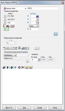
Could someone please explain what the "SNAP" feature under measurement properties in the Auto Feature dialgog box means and when it would be used? Thanks in advance!
Someone corect if I am wrong, I believe its useful when you have a gage point measurement. Say you have a gage point at 1.5 basic and 2.0 +\_.005. So you have to measure it at exactly 1.50 to get the 2.00 measurment. When you the probe takes a hit sometimes it slides off, and it may take a hit near 1.4998, if you select SNAP it will show you the value based on 1.500 hit
The Snap list is automatically enabled in the user interface when working with a Vector Point or a Surface Point feature. For a Circle feature, it is only visible if EnableCircleDCCSnap is set to TRUE in the PC-DMIS Settings Editor. In addition, since snap only functions well after a rough alignment, it is disabled until an alignment is established.
The Snap list determines whether or not measured values "snap to" the theoretical vector for a Vector Point, a Surface Point, and when enabled, for a Circle feature. This simulates a perfect machine staying exactly on the approach vector, not deviating by as much as a micron when measuring the point. If you set this to Yes, then the measured values snap to the theoretical vector with all the deviation along the vector of the point. This is useful for focusing on a deviation along one particular vector.
For example, suppose you want to measure the height (in Z) of a table's top. You don’t really care about your X and Y (secondary and tertiary) axis errors which can occur from machine drift (tunneling error). In this case, with Snap set to Yes, you will only be reporting the Z value. Any errors in X and Y will be ignored as the measured X and Y values will equal their theoretical counterparts.
If I'm understanding right then it would be helpful to have it on if I am reporting the deviation of vector point that is normal to a surface in one axis.... 0,0,1 for example rather than say.... .2551,.36666,.754444. Hope that made sense.
If I'm understanding right then it would be helpful to have it on if I am reporting the deviation of vector point that is normal to a surface in one axis.... 0,0,1 for example rather than say.... .2551,.36666,.754444. Hope that made sense.
Yes, although measuring at v0,0,1 with SNAP probably wont give you a better value vs no snap. Its more designed towards non normal vectors.
All that snap does is put the actual measured point on the nominal vector of the point. Think of it THIS way:
Nominal XYZ along with the nominal IJK will make a 3-D line in space that goes on forever. Now, you measure a point. That point exists in 3D space. Now, make a plane, perpendicular to that 3-D line that goes through the actual measure point. SNAP=ON will give you the point where that 3D line instersects that plane. That's all it does.
SNAP has no effect at all on the "T" axis of a point, it will be exactly the same, ON or OFF.
If you have a point @ X0, Y0, Z0, with a vector of 0,0,1......
NO machine is perfect, ALL machines have SOME amount of drift.
So, that point @ 0,0,0,0,0,1 won't actually get measured at X0Y0, but at some 'real close' location, perhaps X0.011, Y-0.009, and Z 0.351. In either case (ON or OFF) the T axis will report +0.351. However, with SNAP=ON, the report will show it checked at X0 Y0 not at X0.011 Y-0.009. But the "T" is the same, no matter ON/OFF. So, it will also have no effect on 'profile' since 'profile' is based on the "T" axis deviations.
Never use SNAP=ON when doing an ITERATIVE alignment, don't do it, never, not at all, since the TARGET diameter is part of the iterative alignment, using SNAP=ON will screw it up.
You can check a point with SNAP=ON, then you can turn it back off, without re-measuring the point, and you can then see how much drift your machine has. And, it will be different for each and every possible check direction you can think of. the drift will not be the same for vectors of 0,0,1, 0,1,0, 1,0,0, .7071,.7071,0, etc., etc., etc.
What's all this fuss about some PC-DMIS feature to measure points remotely by clapping? Why not just get up and do it manually? Aren't there better things to plug into a wall outlet?
Huh? What's that you say?
It's
"SNAP-on
SNAP-off ???"
Oh, That's very different. Nevermind.
but seriously... thanks for the excellent explanation Matt. Never used it before, but your post is now latest addition to the knowledge reference vault.
+1
I use it for all things NOT iterative. For an almost 30-year-old machine, there isn't much drift (less than 0.0005" I would say) but by using SNAP=ON, my deviations are 'exactly' the vector of the point, and can be used as such in other softwares (like Excel) without the need of exporting the program and importing that into Excel to get the vectors. Very handy for my processes.