hexagon logo

Location of edges with hole pattern as datum


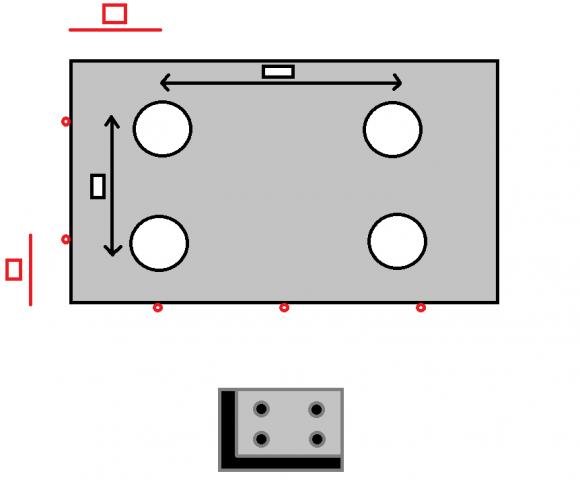
I have manufactured two parts that are going to be assembled. The top part with four holes is going to be assembled to the bottom part consisting of four pins and an elevated L-shape (See Figure), such that when the top part is placed on top of the bottom part they form a smooth plane. To qualify for a correct assembly the holes need to fit with the pins and the left and bottom edge can not intersect the black L-shaped area.

I want to use a pattern of four holes as datum and verify that the points along the edges are not violating this criteria. (Points = red circles in drawing)

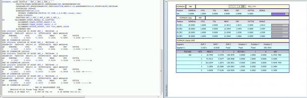
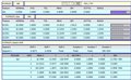
I've measured the size and location of the circles and the points along the edges. How do I define the four holes as a datum and find the location of the edges from there?


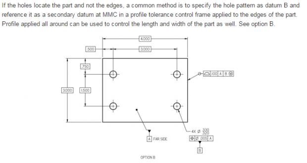
A similar part can be found at this website: http://www.etinews.com/blog/2009/10/01/question-about-specifying-a-position-tolerance-on-a-hole-pattern/ (See Figure)
Parents


  • Datum A is the Far side Plane. Datum B is the hole pattern. For the Line Tolerance for the points at the edge I get a Datum shift: X -0.0071 Y -0.0030 ROT Z 359.7054
    However, to get similar results for the Alignment which is a Best Fit Min/Max of the four holes I need to offset X 0.24 Y -0.47 ROZ Z 359.7054. (See Figure)
    Why are not the datum shift limits the same that I need to apply to the alignment to get the same DEV in the position of the points?

    Attached Files
Reply


  • Datum A is the Far side Plane. Datum B is the hole pattern. For the Line Tolerance for the points at the edge I get a Datum shift: X -0.0071 Y -0.0030 ROT Z 359.7054
    However, to get similar results for the Alignment which is a Best Fit Min/Max of the four holes I need to offset X 0.24 Y -0.47 ROZ Z 359.7054. (See Figure)
    Why are not the datum shift limits the same that I need to apply to the alignment to get the same DEV in the position of the points?

    Attached Files
Children
No Data