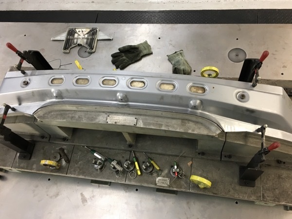
Ok, I'm sure these questions have been asked in some form or another and in fact, I'm sure my last post might have even touched on this topic, but the gurus here tend to espouse knowledge that's a tad bit over my head. So I'm looking for a "For Dummies" type of explanation if one is at all possible. I have a part mounted on a fixture (see the attached pic). I have aligned the fixture to the tooling balls already. I've been told that this is not enough. Also, I need to use the datums for the fcf in the gd&t. I've been made aware that I should do an iterative alignment using the datums. The process for doing so seems simple enough, but what I need is a specific explanation. For the pictured fixture, how exactly do I pick up my datum targets? Do I pick them up with the part on the fixture like in the picture? Or should I pick up my targets before loading and clamping the panel? After picking up my datums, is it necessary to do a separate alignment using the datum targets? Again I apologize to those of you who've responded to similar questions from me in the past, but this is one of those things (along with surface and edge points which I'll ask about later) that they don't cover too well at Hexagon and that are going to help me actually have some confidence in what the **** I'm doing here. Thanks in advance...
Align to the t-balls. Then, without a part on the fixture, go 'find' the net pads. A single point is 'enough' (I usually do minimum of 4 per). Then, look at the screen. Go into DCC mode and program a vector point at each of those touches using the CAD data (you need the cad nominal & vectors). Then using the cad data, program each locator hole, but change them to OUTSIDE not INSIDE (since you have solid pins). For the 2-way slot, pick the slot from the cad using SLOT, then after you get the XYZIJK, change to circle, switch to OUTSIDE and create it.
Make sure the program runs these features. Then make the ITERATIVE alignment selecting all the "A" (net pad) points for level, use the BOTH circles (4-way then 2-way, pick them in THAT order) for the rotate, then pick the 4-way circle for the 'origin'.
Mark the MEASURE ALL ALWAYS box, set your target tolerance to a max of 0.5mm, set your fixture tolerance to 0.05mm and create the alignment. It will ask you several times as you leave the alignment windows if you want to measure the features now, just keep telling it no. Once out, run it.
This. Also, if you are given coordinates for your datum A target points, you can use those points in an auto-feature along with the "Find CAD" (looks like a binocular, make sure to flip vector afterwards to hit the pads), to create your datum points, instead of using measured points to figure out where the points go.