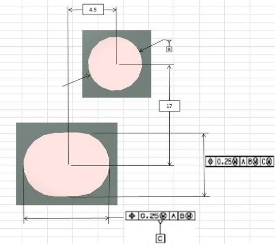
Hello, have been reading this forum for a while now, great source of information. Recently question came up about measuring method so I would like to get advise from the experts. Based on the drawing datum A is the surface of the the stamped part, datum B is is a hole without any positional tolerance and than there is a round slot. Length and width of the slot are dimensioned separately. Length of the slot is marked as datum C and has non diametrical TP 0.25 MMC, A, B MMC with the associated basic dimension of let say 4.5 mm in X direction (looking at the drawing length is in X and width is in Y). Width of the slot has also non diametrical TP 0.25 MMC, A, B MMC, C MMC with the associated basic dimension of let say 17 mm in Y direction. Both hole and the slot are on the same plane A . At some point insert stopped fitting so measurements started at both ends (our company and supplier). My results were showing TP out with center of the slot being only 3.7 mm in X and 17.15 in Y. Company which makes inserts admitted their punch was loose but said position is still in spec. I was setting alignment by measuring 2 radiuses of the slot, creating line between their centers and rotating alignment to it, they simply used 4.5 mm basic to create offset alignment which also automatically made 17.15 in Y shorter and almost perfect. They are also reporting TP of the slot's center in only one direction since in the other direction would be perfect based on the offset. I presented position in 2 directions (thanks to all the posts regarding generic features and variables), also tried explaining that TP callout is not only for the center but any point along slot's axis. I need some confirmation or correction to my method.
measuring the radii of the slot.... less than 180 degrees of a circle, not a good measurement.
If the slot is long enough, measure it as a slot, but as a SQUARE slot, you will get better results.
As for the alignment....
The B datum and the C datum should be zero (perfect) in the directions they locate in. As in, you shouldn't be rotating to the C datum, it is a clocking feature, not a feature to rotate to, the B has to be included with the C, and you can do that either with an offset line OR an iterative alignment.
Base on CAD none of the slot axis are squared with the CS, based on the drawing axis along the length is in X, hole is above and to the right of the center of the slot
Are the diameter and slot in line? If so, I would level to Datum-A, use Datum-B and datum-C to create your alignment line and zero to Datum-B. then use the two radius for length position and the sides of slot for width position.
Using the slot for alignment is way too small and will affect your measurements.
Are the diameter and slot in line? If so, I would level to Datum-A, use Datum-B and datum-C to create your alignment line and zero to Datum-B. then use the two radius for length position and the sides of slot for width position. Using the slot for alignment is way too small and will affect your measurements.
They are not in line, supplier is stamping 2 cavities at the time, I am still getting good TP results on "good" cavity aligning to the slot. I verified my results using vision system and they match.
Base on CAD none of the slot axis are squared with the CS, based on the drawing axis along the length is in X, hole is above and to the right of the center of the slot
If the length is parallel to X, then the slot is an offset as Matt wrote.
So, you need to find the center of the slot length (I would measure as a square slot also). Then create an offset line from B and C, with C offset by the basic. Use that for rotation.
Or, as Matt wrote, use iterative. But then you will have to measure the slot and construct a cast point on the slot, as PC-DMIS will not allow you to use the slot length to rotate to directly.
Thank you for all the replies. Attached is a quick sketch, I omitted sizes of the features itself. If I do offset than one of the 2 positions from the drawing will always be perfect. If that's the way to do it what is the point of 2 separate callouts?