hexagon logo

Does anyone know an easy way to project all the points in a group to a plane?

I have a group of points (a plane for example) and I want to project them all to a plane (simplest case == WORKPLANE). Is there some smart way to do it all at once (a.k.a. "the JEFMAN way") or is it only possible with a loop? I haven't found anything yet...

The object of this is to create a secondary tangent plane perpendicular to the primary by the following method:

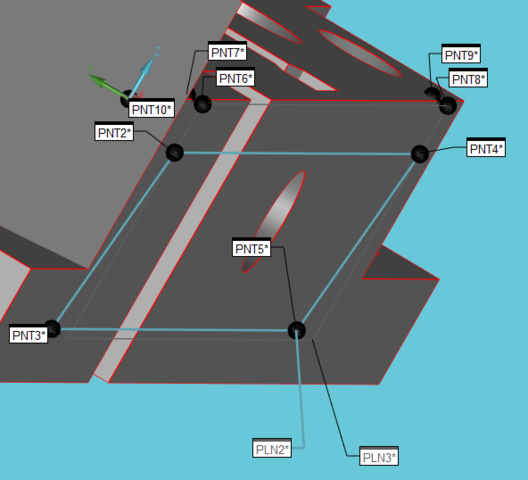
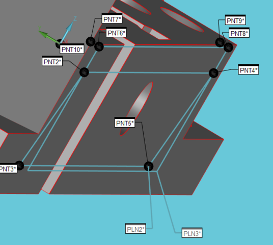
- measure the secondary plane
- project all points up/down to the primary (WORKPLANE)
- construct a tangent plane from the original plane points + the projected points (guaranteed to be perpendicular to the primary as that is our projection direction)

As a follow-up question: How can I use an ARRAY variable in the same way as .HIT[...] in the construction of a tangent plane?
Parents
  • To give you an idea of what this is supposed to accomplish, here's [part of] my test program and some pictures. Just four points, creating a plane that is *not* perpendicular to the primary, projecting the four points and then creating a tangent plane (of all the points) that *is* perpendicular to the primary, touching the 'furthest' of the points of the plane:

    
    PNT2       =FEAT/CONTACT/VECTOR POINT/DEFAULT,CARTESIAN
                THEO/<38,0,-6>,<0,-1,0>
                ACTL/<38,-1,-6>,<0,-1,0>
                TARG/<38,-1,-6>,<0,-1,0>
                SNAP=NO
                REPORT VEC=<0,0,1>,UPDATE VEC=<0,0,1>
                SHOW FEATURE PARAMETERS=NO
                SHOW CONTACT PARAMETERS=NO
    PNT3       =FEAT/CONTACT/VECTOR POINT/DEFAULT,CARTESIAN
                THEO/<38,0,-29>,<0,-1,0>
                ACTL/<38,1,-29>,<0,-1,0>
                TARG/<38,1,-29>,<0,-1,0>
                SNAP=NO
                REPORT VEC=<0,0,1>,UPDATE VEC=<0,0,1>
                SHOW FEATURE PARAMETERS=NO
                SHOW CONTACT PARAMETERS=NO
    PNT4       =FEAT/CONTACT/VECTOR POINT/DEFAULT,CARTESIAN
                THEO/<180,0,-6>,<0,-1,0>
                ACTL/<180,-1,-6>,<0,-1,0>
                TARG/<180,-1,-6>,<0,-1,0>
                SNAP=NO
                REPORT VEC=<0,0,1>,UPDATE VEC=<0,0,1>
                SHOW FEATURE PARAMETERS=NO
                SHOW CONTACT PARAMETERS=NO
    PNT5       =FEAT/CONTACT/VECTOR POINT/DEFAULT,CARTESIAN
                THEO/<180,0,-29>,<0,-1,0>
                ACTL/<180,1,-29>,<0,-1,0>
                TARG/<180,1,-29>,<0,-1,0>
                SNAP=NO
                REPORT VEC=<0,0,1>,UPDATE VEC=<0,0,1>
                SHOW FEATURE PARAMETERS=NO
                SHOW CONTACT PARAMETERS=NO
    
    PLN2       =FEAT/PLANE,CARTESIAN,OUTLINE,NO
                THEO/<109,0,-17.5>,<0,-1,0>
                ACTL/[COLOR=#FF0000]<109,0,-17.5>,<0,-0.9962406,-0.0866296>[/COLOR]
                CONSTR/PLANE,TANGENT,PNT2,PNT3,PNT4,PNT5,,
                MATH_TYPE/CONSTRAINED_MINMAX,BF
    
    [COLOR=#008080]$ this is the part I want to accomplish as one (or a few) single commands, acting on the all the points at the same time. Just think of this on a scanned plane with thousands of points...
    
    PNT6       =FEAT/POINT,CARTESIAN,NO
                THEO/<38,0,0>,<0,0,1>
                ACTL/<38,-1,0>,<0,0,1>
                CONSTR/POINT,PROJ,PNT2,
    PNT7       =FEAT/POINT,CARTESIAN,NO
                THEO/<38,0,0>,<0,0,1>
                ACTL/<38,1,0>,<0,0,1>
                CONSTR/POINT,PROJ,PNT3,
    PNT8       =FEAT/POINT,CARTESIAN,NO
                THEO/<180,0,0>,<0,0,1>
                ACTL/<180,-1,0>,<0,0,1>
                CONSTR/POINT,PROJ,PNT4,
    PNT9       =FEAT/POINT,CARTESIAN,NO
                THEO/<180,0,0>,<0,0,1>
                ACTL/<180,1,0>,<0,0,1>
                CONSTR/POINT,PROJ,PNT5,[/COLOR]
    
    [COLOR=#008080]$ end of problematic area[/COLOR]
    
    PLN3       =FEAT/PLANE,CARTESIAN,OUTLINE,NO
                THEO/<109,0,-8.75>,<0,-1,0>
                ACTL/[COLOR=#0000FF]<109,-1,-8.75>,<0,-1,0>[/COLOR]
                CONSTR/PLANE,TANGENT,PNT2,PNT3,PNT4,PNT5,PNT6,PNT7,PNT8,PNT9,,
                MATH_TYPE/CONSTRAINED_MINMAX,BF


  • What do you mean you don't have the direction yet? Presumably you have at least performed a manual alignment, if not a proper DCC alignment as well. And the points are all (0,-1,0). If they weren't, you would just use the T value (or always just use the T value regardless.)

    In either case, with PC-DMIS, you would almost always be required to have a rough alignment first (PC-DMIS just doesn't have the tools yet, like PolyWorks does). So, this would be (at the earliest) your 3rd alignment, or if you are using Xact, this would be the feature that you end up using as your Defined Datum. You could even do "iterations" of the *Find Max, create generic on Max point at defined IJK* process until you were happy with it.

    I get what you're asking for, but I think PC-DMIS just isn't well equipped to do so.
Reply
  • What do you mean you don't have the direction yet? Presumably you have at least performed a manual alignment, if not a proper DCC alignment as well. And the points are all (0,-1,0). If they weren't, you would just use the T value (or always just use the T value regardless.)

    In either case, with PC-DMIS, you would almost always be required to have a rough alignment first (PC-DMIS just doesn't have the tools yet, like PolyWorks does). So, this would be (at the earliest) your 3rd alignment, or if you are using Xact, this would be the feature that you end up using as your Defined Datum. You could even do "iterations" of the *Find Max, create generic on Max point at defined IJK* process until you were happy with it.

    I get what you're asking for, but I think PC-DMIS just isn't well equipped to do so.
Children
No Data