hexagon logo

Diameter of a Cylinder -> Size Feature vs constructed cylinder

Dear PC-DMIS users, colleagues, and experts,

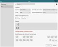
In the last months, in the company where I'm currently working, we've updated our PC-DMIS software to one of the newer versions (2018 R1), and have found a new possibility to report sizes with all the ISO modifiers integrated. For us this is great news, since now we can apply the modifiers directly on the measure rather than through the elements construction.


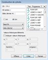
Doing so, we've found that using the "enveloppe" requirement, that for an external diameter should grant the GN for the USL, and LP for the LSL, gives the same result as demanding each modifier separately (which is good), however, the GN hands a different value than when constructing by Best Fit & Min Circumscribed cylinder (same points, same element, by scanning and then constructed).


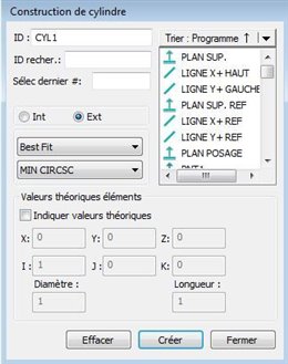
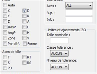
and then demanding the diameter through the loc feature

We observed that the result is the same regardless of alignment, we also observed that the Mean Squares and GG modifier result on the same diameter (which is at is should be).
We tried the same idea with the GX diameter, and a Max Inscribed Best Fit Cylinder, and the problem is reproduced. The value for diameter is different in a magnitude close to 0.01 mm.

I'd like to know which of our assumptions is wrong, (that a min circumscribed best fit cylinder should be equal to GN for example, or maybe the diameter calculation through the localization feature), and why is it wrong. Or, if it may just be a problem of our programming that can be solved.

As a bonus question, I'd like to know if the size feature with modifiers that I show in the first screenshot will be available for two parallel planes (or it already is and we didn't find how to use it correctly, which is certainly possible).

Thank you very much for the time taken to read this far.

Best regards,

Álvaro

Attached Files
Parents
  • Hey Alvaro

    I noticed the same issue a few months ago. However the differences where much smaller. If I remember correctly the max difference between the 2 approaches were around 0.001mm.
    I asked our support in Germany about it and they also didn't know the answer but asked the programmers at Wilcox.

    This is the answer they gave us:
    Re: different values between location dimension and size dimension for max_insc and min_circsc
    It is a different calculation by design. We are using constrained L2 math for Maximum Inscribed and Minimum Circumscribed in the Size dimension but are still using the original Max_Inscribed and Min_Circumscribed math everywhere else in PC-DMIS. That answers your question, but the next question is probably why? Daniel and I are members of ASME and ISO committee's and have been involved in studies that resulted in changes in the standards. Since the new ASME and ISO standards are not published yet, I am apprehensive about making any further changes in PC-DMIS because it would impact program migration and prompt questions from customers. The Size dimension command is new so does not affect program migration but does causes confusion in the case you describe in this report (comparing with math from other commands). The results from constrained L2 are more precise and more repeatable, so we are planning on changing the math in other areas of PC-DMIS beginning in 2019 R2. I also expect ASME Y14.5, Y14.5.1 and ISO 5459 to be Published by then.


    Regarding your second question, you first have to create a width feature. Then you'll be able to select it.

    Best regards

    Aaron
Reply
  • Hey Alvaro

    I noticed the same issue a few months ago. However the differences where much smaller. If I remember correctly the max difference between the 2 approaches were around 0.001mm.
    I asked our support in Germany about it and they also didn't know the answer but asked the programmers at Wilcox.

    This is the answer they gave us:
    Re: different values between location dimension and size dimension for max_insc and min_circsc
    It is a different calculation by design. We are using constrained L2 math for Maximum Inscribed and Minimum Circumscribed in the Size dimension but are still using the original Max_Inscribed and Min_Circumscribed math everywhere else in PC-DMIS. That answers your question, but the next question is probably why? Daniel and I are members of ASME and ISO committee's and have been involved in studies that resulted in changes in the standards. Since the new ASME and ISO standards are not published yet, I am apprehensive about making any further changes in PC-DMIS because it would impact program migration and prompt questions from customers. The Size dimension command is new so does not affect program migration but does causes confusion in the case you describe in this report (comparing with math from other commands). The results from constrained L2 are more precise and more repeatable, so we are planning on changing the math in other areas of PC-DMIS beginning in 2019 R2. I also expect ASME Y14.5, Y14.5.1 and ISO 5459 to be Published by then.


    Regarding your second question, you first have to create a width feature. Then you'll be able to select it.

    Best regards

    Aaron
Children
No Data