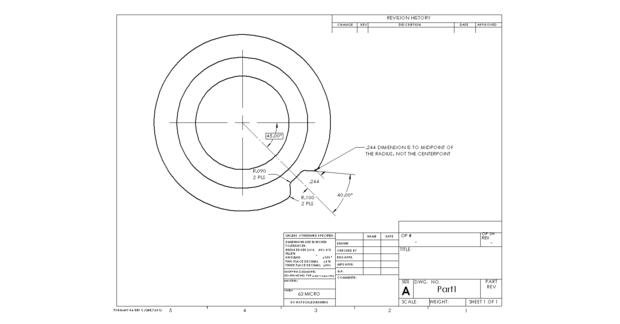
Hello everyone. I am having trouble trying to dimension to the midpoint of this radius callout, rather than the center. In the drawing, shown below, there is the .244 dimension from the centerline of the 45° BSC angle to the midpoint of the radius. I have adjusted my alignment to fit the 45° BSC angle and have measured a line on the 40° surface, measured the radius as vector points and a constructed circle, and have made a cast point to the cylinder (the origin). I have tried making a pierce point from the line, to the origin (cast point), to the circle (.100 radius) but it is not exactly at nominal. Is there a way to properly inspect this dimension?
Kinda hard to see, but it looks like the 0.244 dim is to the tangent point of the radius and the 40° surface. Is your line direction on that surface pointing towards the radius? if yes, then pierce point from line to constructed circle. If not, then construct a line in the opposite direction.
Kinda hard to see, but it looks like the 0.244 dim is to the tangent point of the radius and the 40° surface. Is your line direction on that surface pointing towards the radius? if yes, then pierce point from line to constructed circle. If not, then construct a line in the opposite direction.
The callout is not to the tangency point but to the midpoint of the arc of the radius. I can't dimension to the centerpoint of the measured circle because it would be off. I was debating just making a vector point from the theoretical X & Y locations (found from the Solidworks CAD file) but I am not sure if that is the best way to go about it. It seems like there would be a lot of room for error that way.
I know it's not a full 90°. Depending on the length of the arc, DMIS could have a hard time calculating the data accurately, correctly, and repeatable.