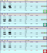
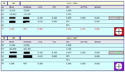
Recently we had a dispute, for many years we measured a part according to the program sent to us by our collegues from another country, I am forbidden to doubt their qualifications. They used an legacy method for measuring TP, everything was in order until we started having problems with the cnc producing this part, some holes went out of tolerance, for the sake of interest I tried to apply xact and for these measurements it is not ideal but in the tolerance zone, now we do not know what to do, because our parts do not pass through the old dimensions, but the repair service says that it cannot find the problem, I am still a beginner and do not want to go against great minds, but I just wonder how it would be more correct. Here measurements of the same part, and we use iterative alignment.
Have a great sunny weekend everyone
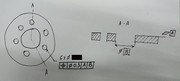
This one looks like it has been in discussion for a while and it is quite a common cause of confusion so I thought I'd help out. As many people have said, the original program is wrong. Based on your sketch of the part and the position call out you are trying to measure, the correct approach should be as follows....
1) Measure the top face (datum A) as a plane, taking enough points to capture the form error (flatness).
2) Measure the centre bore (datum B) as a cylinder.
3) Measure the 6 x holes as cylinders.
4) Dimension the holes.
To dimension using XactMeasure (feature control frame reporting), add a DATDEF command defining the top plane as datum A. Add another DATDEF command defining the centre cylinder as datum B. INSERT>DIMENSION>POSITION. Select all 6 holes and build the feature control frame - position, Ø0.3 to A (primary), B (secondary).
To dimension using Legacy dimensions you need to create the A,B alignment. Level ZPLUS to the top plane and origin Z. Origin X & Y to the centre cylinder. Click the BESTFIT button. Select all 6 holes, 2D no translation, 2D plane = ZPLUS then click COMPUTE and OK. INSERT>DIMENSION>POSITION, select all 6 holes, enter the 0.3 tolerance and hit create - you do not need to select datums as it reports relative to your current alignment which simulates the datum reference frame.
Both methods should yield the same results but it is very important that the nominal (THEO) X,Y,Z,I,J & K values are correct for all features, especially if you have had to manually type them in.
My justification for saying the original program is wrong is this...
There is no tertiary datum for the position call out - it is simply |Ø0.3|A|B|. A is the primary and B is the secondary so we must level to A and origin to B but since there is no rotational constraint, the 6 holes are free to rotate around B until they are optimized. The original program ignores this and constrains rotation using one of the holes rather than best fitting all 6 as a set. The original program also measures datum B and the 6 holes as circles and as such is not satisfying the position requirement. Position relates to the entire axis of the feature. By measuring the holes as circles it is only evaluating a point at whatever depth the hole was measured. It is ignoring any orientation error that may be present and could result in passing parts that are actually bad and would not assemble. In addition to this, in the legacy position dimensions, it references the two datums in the wrong order - D1 references datum B when it should be A and D2 references A when it should be B.
In terms of my credentials to back up this evaluation. I have been a CMM programmer for over 20 years having worked as an inspector, (5 years) quality engineer (5 years), hexagon applications engineer (8 years) and software technical specialist (2 years). I have taught both first principles measurement and GD&T classes for Hexagon and on behalf of the National Physical Laboratory (UK) and I have been heavily involved in the development of the new geometric tolerance command for PC-Dmis 2020 R2.