
Have a great sunny weekend everyone


Your Products have been synced, click here to refresh
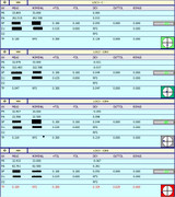
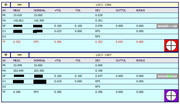
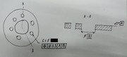
In both cases A level, B origin, C one of the six holes to Y- according to drawing
PNT1 =FEAT/CONTACT/VECTOR POINT/DEFAULT,CARTESIAN
THEO/<-13.239,32.138,10.2>,<0,0,1>
ACTL/<121.514,277.054,-720.653>,<0.0000705,-0.0006548,0.9999998>
TARG/<-13.239,32.138,10.2>,<0,0,1>
SHOW FEATURE PARAMETERS=YES
SURFACE=THEO_THICKNESS,0
MEASURE MODE=NOMINALS
RMEAS=NONE,NONE,NONE
AUTO WRIST=NO
GRAPHICAL ANALYSIS=NO
FEATURE LOCATOR=NO,NO,""
SHOW CONTACT PARAMETERS=YES
AVOIDANCE MOVE=BOTH,DISTANCE=20
SHOW HITS=NO
PNT2 =FEAT/CONTACT/VECTOR POINT/DEFAULT,CARTESIAN
THEO/<-21.993,-25.32,10.2>,<0,0,1>
ACTL/<121.121,218.934,-720.688>,<0.0000705,-0.0006548,0.9999998>
TARG/<-21.993,-25.32,10.2>,<0,0,1>
SHOW FEATURE PARAMETERS=YES
SURFACE=THEO_THICKNESS,0
MEASURE MODE=NOMINALS
RMEAS=NONE,NONE,NONE
AUTO WRIST=NO
GRAPHICAL ANALYSIS=NO
FEATURE LOCATOR=NO,NO,""
SHOW CONTACT PARAMETERS=YES
AVOIDANCE MOVE=BOTH,DISTANCE=20
SHOW HITS=NO
PNT3 =FEAT/CONTACT/VECTOR POINT/DEFAULT,CARTESIAN
THEO/<32.524,-3.431,10.2>,<0,0,1>
ACTL/<171.92,248.445,-720.676>,<0.0000705,-0.0006548,0.9999998>
TARG/<32.524,-3.431,10.2>,<0,0,1>
SHOW FEATURE PARAMETERS=YES
SURFACE=THEO_THICKNESS,0
MEASURE MODE=NOMINALS
RMEAS=NONE,NONE,NONE
AUTO WRIST=NO
GRAPHICAL ANALYSIS=NO
FEATURE LOCATOR=NO,NO,""
SHOW CONTACT PARAMETERS=YES
AVOIDANCE MOVE=BOTH,DISTANCE=20
SHOW HITS=NO
PNT4 =FEAT/CONTACT/VECTOR POINT/DEFAULT,CARTESIAN
THEO/<18.15,27.13,10.2>,<0,0,1>
ACTL/<153.297,276.618,-720.65>,<0.0000705,-0.0006548,0.9999998>
TARG/<18.15,27.13,10.2>,<0,0,1>
SHOW FEATURE PARAMETERS=YES
SURFACE=THEO_THICKNESS,0
MEASURE MODE=NOMINALS
RMEAS=NONE,NONE,NONE
AUTO WRIST=NO
GRAPHICAL ANALYSIS=NO
FEATURE LOCATOR=NO,NO,""
SHOW CONTACT PARAMETERS=YES
AVOIDANCE MOVE=BOTH,DISTANCE=20
SHOW HITS=NO
B CIR =FEAT/CONTACT/CIRCLE/DEFAULT,CARTESIAN,IN,LEAST_SQR
THEO/<0,0,10.2>,<0,0,1>,45
ACTL/<139.235,247.162,-720.657>,<0.0002473,-0.0008993,0.9999996>,45.032
TARG/<0,0,10.2>,<0,0,1>
START ANG=0,END ANG=0
ANGLE VEC=<1,0,0>
DIRECTION=CCW
SHOW FEATURE PARAMETERS=YES
REMEASURE=NO
SURFACE=THEO_THICKNESS,0
MEASURE MODE=NOMINALS
RMEAS=NONE,NONE,NONE
AUTO WRIST=NO
GRAPHICAL ANALYSIS=NO
FEATURE LOCATOR=NO,NO,""
SHOW CONTACT PARAMETERS=YES
NUMHITS=4,DEPTH=3,PITCH=0
SAMPLE HITS=3,SPACER=3
AVOIDANCE MOVE=BOTH,DISTANCE=20
FIND HOLE=DISABLED,ONERROR=NO,READ POS=NO
SHOW HITS=NO
C CIR =FEAT/CONTACT/CIRCLE/DEFAULT,CARTESIAN,IN,LEAST_SQR
THEO/<-4.307,-32.724,10.2>,<0,0,1>,11.5
ACTL/<139.704,214.105,-720.693>,<0.000345,-0.0023923,0.9999971>,11.548
TARG/<-4.307,-32.718,10.2>,<0,0,1>
START ANG=0,END ANG=360
ANGLE VEC=<1,0,0>
DIRECTION=CCW
SHOW FEATURE PARAMETERS=YES
REMEASURE=NO
SURFACE=THEO_THICKNESS,0
MEASURE MODE=NOMINALS
RMEAS=NONE,NONE,NONE
AUTO WRIST=NO
GRAPHICAL ANALYSIS=NO
FEATURE LOCATOR=NO,NO,""
SHOW CONTACT PARAMETERS=YES
NUMHITS=4,DEPTH=3,PITCH=0
SAMPLE HITS=3,SPACER=3
AVOIDANCE MOVE=BOTH,DISTANCE=20
FIND HOLE=DISABLED,ONERROR=NO,READ POS=NO
SHOW HITS=NO
A1 =ALIGNMENT/START,RECALL:STARTUP,LIST=YES
ALIGNMENT/ITERATE
PNT TARGET RAD=0.1,START LABEL=,FIXTURE TOL=0.05,ERROR LABEL=
MEAS ALL FEAT=ALWAYS,MAX ITERATIONS=1,LEVEL AXIS=ZAXIS,ROTATE AXIS=XAXIS,ORIGIN AXIS=YAXIS
LEVEL=PNT1,PNT2,PNT3,PNT4,,
ROTATE=B CIR,C CIR,,
ORIGIN=B CIR,,
ALIGNMENT/END
MODE/DCC
CLEARP/ZPLUS,35,ZPLUS,35,ON
PNT5 =FEAT/POINT,CARTESIAN
THEO/<5.216,32.796,0.118>,<0,0,1>
ACTL/<5.217,32.796,-0.659>,<0,0,1>
MEAS/POINT,1,WORKPLANE
MOVE/CLEARPLANE
HIT/BASIC,NORMAL,<5.216,32.796,0.118>,<0,0,1>,<5.217,3 2.796,-0.659>,USE THEO=YES
ENDMEAS/
PNT6 =FEAT/POINT,CARTESIAN
THEO/<-27.029,20.012,0.111>,<0,0,1>
ACTL/<-27.029,20.012,-0.652>,<0,0,1>
MEAS/POINT,1,WORKPLANE
MOVE/CLEARPLANE
HIT/BASIC,NORMAL,<-27.029,20.012,0.111>,<0,0,1>,<-27.029,20.012,-0.652>,USE THEO=YES
ENDMEAS/
PNT7 =FEAT/POINT,CARTESIAN
THEO/<-5.7,-34.325,0.074>,<0,0,1>
ACTL/<-5.7,-34.328,-0.609>,<0,0,1>
MEAS/POINT,1,WORKPLANE
MOVE/CLEARPLANE
HIT/BASIC,NORMAL,<-5.7,-34.325,0.074>,<0,0,1>,<-5.7,-34.328,-0.609>,USE THEO=YES
ENDMEAS/
PNT8 =FEAT/POINT,CARTESIAN
THEO/<29.959,11.994,0.102>,<0,0,1>
ACTL/<29.96,11.995,-0.627>,<0,0,1>
MEAS/POINT,1,WORKPLANE
MOVE/CLEARPLANE
HIT/BASIC,NORMAL,<29.959,11.994,0.102>,<0,0,1>,<29.96, 11.995,-0.627>,USE THEO=YES
ENDMEAS/
A PLN =FEAT/PLANE,CARTESIAN,TRIANGLE,NO
THEO/<0.611,7.62,0.101>,<0.0000598,-0.0006592,0.9999998>
ACTL/<0.612,7.618,-0.637>,<-0.0003234,0.0007474,0.9999997>
CONSTR/PLANE,BFRE,PNT5,PNT6,PNT7,PNT8,,
OUTLIER_REMOVAL/OFF,3
FILTER/OFF,WAVELENGTH=0
MOVE/CLEARPLANE
A2 =ALIGNMENT/START,RECALL:A1,LIST=YES
ALIGNMENT/LEVEL,ZPLUS,A PLN
ALIGNMENT/TRANS,ZAXIS,A PLN
ALIGNMENT/END
dim loc3= position of circle c cir units=mm ,$
graph=off text=off mult=10.00 output=both fit to datums=off dev perpen centerline=off display=diameter
ax meas nominal +tol -tol bonus dev outtol
pr 33.053 33.000 0.053
pa 262.512 262.500 0.012
df 11.548 11.500 0.100 0.100 0.048 0.000 ------#--
d1 45.032 45.000 0.025 0.000 circle b cir at rfs
d2 plane a pln at rfs
tp 0.107 rfs 0.300 0.000 0.107 0.000 ---#-----
end of dimension loc3
cir3 =feat/contact/circle/default,cartesian,in,least_sqr
theo/<26.181,-20.089,10.125>,<-0.0006008,0.0002778,0.9999998>,11.5
actl/<26.191,-20.164,10.805>,<0.0020137,-0.0017493,0.9999964>,11.542
targ/<26.175,-20.086,10.125>,<-0.0006008,0.0002778,0.9999998>
start ang=0,end ang=360
angle vec=<0.5000004,0.8660252,0.0000598>
direction=ccw
show feature parameters=yes
remeasure=no
surface=theo_thickness,0
measure mode=nominals
rmeas=none,none,none
auto wrist=no
circular moves=no
clearplane=no
graphical analysis=no
feature locator=no,no,""
show contact parameters=yes
numhits=4,depth=3,pitch=0
sample hits=3,spacer=3
avoidance move=both,distance=20
find hole=disabled,onerror=no,read pos=no
show hits=no
dim loc3= position of circle cir3 units=mm ,$
graph=off text=off mult=10.00 output=both fit to datums=off dev perpen centerline=off display=diameter
ax meas nominal +tol -tol bonus dev outtol
pr 33.042 33.000 0.042
pa 322.424 322.500 -0.076
df 11.542 11.500 0.100 0.100 0.042 0.000 ------#--
d1 45.032 45.000 0.025 0.000 circle b cir at rfs
d2 plane a pln at rfs
tp 0.121 rfs 0.300 0.000 0.121 0.000 ---#-----
end of dimension loc3
cir4 =feat/contact/circle/default,cartesian,in,least_sqr
theo/<30.488,12.629,10.125>,<-0.000541,-0.0003814,0.9999998>,11.5
actl/<30.491,12.576,10.833>,<0.0018994,0.0004675,0.9999 981>,11.549
targ/<30.483,12.625,10.125>,<-0.000541,-0.0003814,0.9999998>
start ang=0,end ang=360
angle vec=<-0.4999996,0.8660256,0.0000598>
direction=ccw
show feature parameters=yes
remeasure=no
surface=theo_thickness,0
measure mode=nominals
rmeas=none,none,none
auto wrist=no
circular moves=no
clearplane=no
graphical analysis=no
feature locator=no,no,""
show contact parameters=yes
numhits=4,depth=3,pitch=0
sample hits=3,spacer=3
avoidance move=both,distance=20
find hole=disabled,onerror=no,read pos=no
show hits=no
dim loc3= position of circle cir4 units=mm ,$
graph=off text=off mult=10.00 output=both fit to datums=off dev perpen centerline=off display=diameter
ax meas nominal +tol -tol bonus dev outtol
pr 32.984 33.000 -0.016
pa 22.440 22.500 -0.060
df 11.549 11.500 0.100 0.100 0.049 0.000 ------#--
d1 45.032 45.000 0.025 0.000 circle b cir at rfs
d2 plane a pln at rfs
tp 0.076 rfs 0.300 0.000 0.076 0.000 --#------
end of dimension loc3
cir5 =feat/contact/circle/default,cartesian,in,least_sqr
theo/<4.307,32.718,10.125>,<0.0000598,-0.0006592,0.9999998>,11.5
actl/<4.305,32.665,10.859>,<-0.0000744,0.0006359,0.9999998>,11.55
targ/<4.308,32.711,10.125>,<0.0000598,-0.0006592,0.9999998>
start ang=0,end ang=360
angle vec=<-1,0.0000005,0.0000598>
direction=ccw
show feature parameters=yes
remeasure=no
surface=theo_thickness,0
measure mode=nominals
rmeas=none,none,none
auto wrist=no
circular moves=no
clearplane=no
graphical analysis=no
feature locator=no,no,""
show contact parameters=yes
numhits=4,depth=3,pitch=0
sample hits=3,spacer=3
avoidance move=both,distance=20
find hole=disabled,onerror=no,read pos=no
show hits=no
dim loc3= position of circle cir5 units=mm ,$
graph=off text=off mult=10.00 output=both fit to datums=off dev perpen centerline=off display=diameter
ax meas nominal +tol -tol bonus dev outtol
pr 32.961 33.000 -0.039
pa 82.502 82.500 0.002
df 11.550 11.500 0.100 0.100 0.050 0.000 ------#--
d1 45.032 45.000 0.025 0.000 circle b cir at rfs
d2 plane a pln at rfs
tp 0.078 rfs 0.300 0.000 0.078 0.000 --#------
end of dimension loc3
cir6 =feat/contact/circle/default,cartesian,in,least_sqr
theo/<-26.181,20.089,10.125>,<0.0006008,-0.0002778,0.9999998>,11.5
actl/<-26.185,20.019,10.86>,<-0.0007274,-0.0007158,0.9999995>,11.546
targ/<-26.175,20.086,10.125>,<0.0006008,-0.0002778,0.9999998>
start ang=0,end ang=360
angle vec=<-0.5000004,-0.8660252,0.0000598>
direction=ccw
show feature parameters=yes
remeasure=no
surface=theo_thickness,0
measure mode=nominals
rmeas=none,none,none
auto wrist=no
circular moves=no
clearplane=no
graphical analysis=no
feature locator=no,no,""
show contact parameters=yes
numhits=4,depth=3,pitch=0
sample hits=3,spacer=3
avoidance move=both,distance=20
find hole=disabled,onerror=no,read pos=no
show hits=no
dim loc3= position of circle cir6 units=mm ,$
graph=off text=off mult=10.00 output=both fit to datums=off dev perpen centerline=off display=diameter
ax meas nominal +tol -tol bonus dev outtol
pr 32.972 33.000 -0.028
pa 142.585 142.500 0.085
df 11.546 11.500 0.100 0.100 0.046 0.000 ------#--
d1 45.032 45.000 0.025 0.000 circle b cir at rfs
d2 plane a pln at rfs
tp 0.112 rfs 0.300 0.000 0.112 0.000 ---#-----
end of dimension loc3
cir7 =feat/contact/circle/default,cartesian,in,least_sqr
theo/<-30.488,-12.629,10.125>,<0.000541,0.0003814,0.9999998>,11.5
actl/<-30.486,-12.701,10.835>,<-0.000272,-0.0015425,0.9999988>,11.559
targ/<-30.483,-12.625,10.125>,<0.000541,0.0003814,0.9999998>
start ang=0,end ang=360
angle vec=<0.4999996,-0.8660256,0.0000598>
direction=ccw
show feature parameters=yes
remeasure=no
surface=theo_thickness,0
measure mode=nominals
rmeas=none,none,none
auto wrist=no
circular moves=no
clearplane=no
graphical analysis=no
feature locator=no,no,""
show contact parameters=yes
numhits=4,depth=3,pitch=0
sample hits=3,spacer=3
avoidance move=both,distance=20
find hole=disabled,onerror=no,read pos=no
show hits=no
dim loc3= position of circle cir7 units=mm ,$
graph=off text=off mult=10.00 output=both fit to datums=off dev perpen centerline=off display=diameter
ax meas nominal +tol -tol bonus dev outtol
pr 33.024 33.000 0.024
pa 202.591 202.500 0.091
df 11.559 11.500 0.100 0.100 0.059 0.000 -------#-
d1 45.032 45.000 0.025 0.000 circle b cir at rfs
d2 plane a pln at rfs
tp 0.115 rfs 0.300 0.000 0.115 0.000 ---#-----
end of dimension loc3


| © 2024 Hexagon AB and/or its subsidiaries. | Privacy Policy | Cloud Services Agreement |


