Good Morning! I'm new to using CAD models. I only used them in class. I created a manual plane, line, point alignment to make the model aligned with the machine. The problem I'm having is when I change my alignment or workplane, my points are no longer aligned with my model. They are offset and mess up my dimensions. Do I need to continually redo the manual alignment to keep everything where it should be or am I missing something else? Thanks in advance!
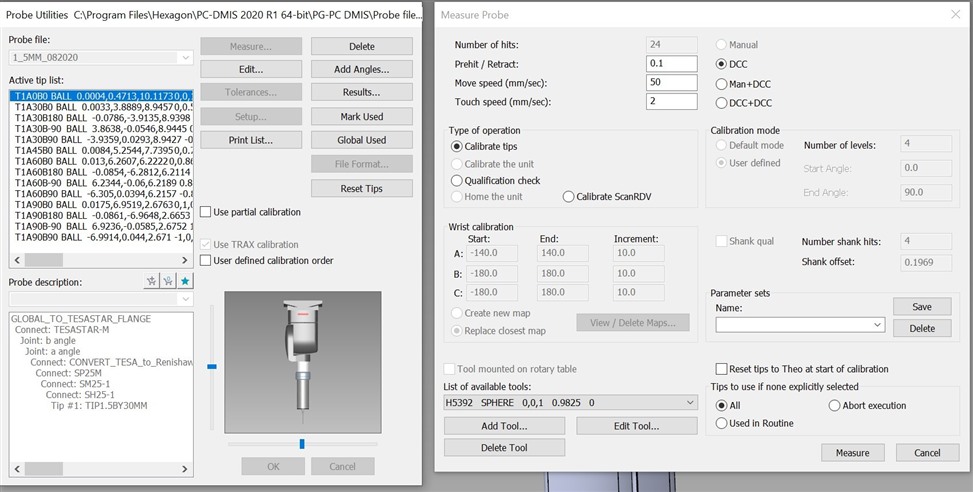
Quick question. I noticed in
DAN_M pic of the calibration details (great stuff) that almost everything in the 'Measure Probe' window is NOT greyed out. With mine, everything is greyed out unless I select a Partial Calibration. I'm just curious, is this something that I'm missing? I believe I have calibration issues. At times I feel like I have it down, then at other times I feel confused because my A90B180 tip will take a point in a different Z location than if I took that same hit in A90B0 or A0B0, etc. Sorry if this isn't truly related, I can make a new post.
pguillory if you mean that the A90/B180 takes hits off centre to the sphere then that is usually due to an error in the probe build. Essentially PC-Dmis thinks the probe is a different length to what it actually is because you have either added an additional component to the build or left one out. A common mistake is confusing 20mm and 21mm styli or forgetting to include an adaptor or extension in the component list. If you're absolutely sure the physical probe build matches the component list then it could be that the probe file contains bad offsets - normally caused by not correctly following the "master probe" approach that has been discussed at length in many posts on this forum. If this is the case you would need to either reset your tips or in extreme cases, delete and re-create your probe file.
pguillory if you mean that the A90/B180 takes hits off centre to the sphere then that is usually due to an error in the probe build. Essentially PC-Dmis thinks the probe is a different length to what it actually is because you have either added an additional component to the build or left one out. A common mistake is confusing 20mm and 21mm styli or forgetting to include an adaptor or extension in the component list. If you're absolutely sure the physical probe build matches the component list then it could be that the probe file contains bad offsets - normally caused by not correctly following the "master probe" approach that has been discussed at length in many posts on this forum. If this is the case you would need to either reset your tips or in extreme cases, delete and re-create your probe file.