Have a question regarding the new software since I installed it recently a lot of parts I deal with have datum target alignments where I'll use the iterative function in the past for example if I had four targets on offset areas for Datum A I would construct a feature set from these and define it as A before doing the iterative alignment, this would allow me to use Xact Measure to call back to datum A. In the new upgrade it tells me I cant make a constructed feature set my primary datum, so other then picking one of the target areas and offsetting all other points to the same height then constructing my plane, has anyone else run into this issue or have knowledge on it?
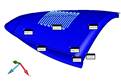
Although you use the datum target points for your iterative alignment, they do not necessarily represent the individual datums called out on the drawing - moreover, they are supposed to be used in conjunction with each other to define a datum reference frame. If you think of it in fixturing terms, imagine three mutually perpendicular surface plates representing X, Y and Z - these are the datums. If you were to slide a completely free-form shape up against these surface plates until it made contact with all three such that it's movement was fully constrained, the contact points between the part and the surface plates would be the datum target points. You would not try to measure dimensions on the part directly from those points, you would measure from the surface plates - the datums. To simulate this approach in PC-Dmis you should use the iterative alignment functionality to probe the datum target points and establish the alignment that represents the datum reference frame. You should then construct alignment planes for each axis and define those planes as the datum features. Those datum planes can then be referenced for subsequent dimensions. It is important to remember that in cases where hit data is supplied for datum features, the geometric tolerance command will ignore the current alignment and feature fitting algorithms and instead, perform it's own fit calculations based on the datum math options. The fit calculations can only function correctly for known geometric shapes (planes, cones, spheres, cylinders, circles etc.). By defining datum features without hit data as we would do in this case, we are over-riding that behaviour and forcing the command to use our alignment. This would be the desired behaviour when datum targets are specified since the geometric tolerance command can not know how to fit the targets themselves - it would require additional information from the drawing such as the type, shape and size of contact.
Example
PNT1 =FEAT/CONTACT/SURFACE POINT/DEFAULT,CARTESIAN
THEO/<107.1518,-24.4875,26.802>,<-0.15902,0.925419,-0.3439656>
ACTL/<107.1518,-24.4875,26.802>,<-0.15902,0.925419,-0.3439656>
TARG/<107.1518,-24.4875,26.802>,<-0.15902,0.925419,-0.3439656>
SHOW FEATURE PARAMETERS=NO
SHOW CONTACT PARAMETERS=NO
PNT2 =FEAT/CONTACT/SURFACE POINT/DEFAULT,CARTESIAN
THEO/<109.457,-24.432,25.4032>,<-0.1866582,0.9584977,-0.2155015>
ACTL/<109.457,-24.432,25.4032>,<-0.1866582,0.9584977,-0.2155015>
TARG/<109.457,-24.432,25.4032>,<-0.1866582,0.9584977,-0.2155015>
SHOW FEATURE PARAMETERS=NO
SHOW CONTACT PARAMETERS=NO
PNT3 =FEAT/CONTACT/SURFACE POINT/DEFAULT,CARTESIAN
THEO/<108.9884,-24.9683,24.1326>,<-0.420581,0.8279228,-0.3710194>
ACTL/<108.9884,-24.9683,24.1326>,<-0.420581,0.8279228,-0.3710194>
TARG/<108.9884,-24.9683,24.1326>,<-0.420581,0.8279228,-0.3710194>
SHOW FEATURE PARAMETERS=NO
SHOW CONTACT PARAMETERS=NO
PNT4 =FEAT/CONTACT/SURFACE POINT/DEFAULT,CARTESIAN
THEO/<108.1769,-24.6685,26.8044>,<0.5293037,0.194161,0.8259171>
ACTL/<108.1769,-24.6685,26.8044>,<0.5293037,0.194161,0.8259171>
TARG/<108.1769,-24.6685,26.8044>,<0.5293037,0.194161,0.8259171>
SHOW FEATURE PARAMETERS=NO
SHOW CONTACT PARAMETERS=NO
PNT5 =FEAT/CONTACT/SURFACE POINT/DEFAULT,CARTESIAN
THEO/<109.8632,-24.5643,25.6238>,<0.5622955,0.2935389,0.7730839>
ACTL/<109.8632,-24.5643,25.6238>,<0.5622955,0.2935389,0.7730839>
TARG/<109.8632,-24.5643,25.6238>,<0.5622955,0.2935389,0.7730839>
SHOW FEATURE PARAMETERS=NO
SHOW CONTACT PARAMETERS=NO
PNT6 =FEAT/CONTACT/SURFACE POINT/DEFAULT,CARTESIAN
THEO/<110.1279,-24.7426,25.0337>,<0.851129,0.2054012,-0.4831043>
ACTL/<110.1279,-24.7426,25.0337>,<0.851129,0.2054012,-0.4831043>
TARG/<110.1279,-24.7426,25.0337>,<0.851129,0.2054012,-0.4831043>
SHOW FEATURE PARAMETERS=NO
SHOW CONTACT PARAMETERS=NO
A1 =ALIGNMENT/START,RECALL:STARTUP,LIST=YES
ALIGNMENT/ITERATE
PNT TARGET RAD=0.005,START LABEL=,FIXTURE TOL=0,ERROR LABEL=
MEAS ALL FEAT=ALWAYS,MAX ITERATIONS=99,LEVEL AXIS=YAXIS,ROTATE AXIS=ZAXIS,ORIGIN AXIS=XAXIS
LEVEL=PNT1,PNT2,PNT3,,
ROTATE=PNT4,PNT5,,
ORIGIN=PNT6,,
ALIGNMENT/END
PLN_A =FEAT/PLANE,CARTESIAN,TRIANGLE,NO
THEO/<0,0,0>,<0,0,1>
ACTL/<0,0,0>,<0,0,1>
CONSTR/PLANE,ALIGN,ZPLUS
PLN_B =FEAT/PLANE,CARTESIAN,TRIANGLE,NO
THEO/<0,0,0>,<1,0,0>
ACTL/<0,0,0>,<1,0,0>
CONSTR/PLANE,ALIGN,XPLUS
PLN_C =FEAT/PLANE,CARTESIAN,TRIANGLE,NO
THEO/<0,0,0>,<0,1,0>
ACTL/<0,0,0>,<0,1,0>
CONSTR/PLANE,ALIGN,YPLUS
DATDEF/A,FEATURES=PLN_A,,
DATDEF/B,FEATURES=PLN_B,,
DATDEF/C,FEATURES=PLN_C,,
SCN1 =FEAT/SCAN,PATCH,NUMBER OF HITS=213,SHOW HITS=NO,SHOWALLPARAMS=NO
MEAS/SCAN
BASICSCAN/LINE,NUMBER OF HITS=14,SHOW HITS=NO,SHOWALLPARAMS=NO
ENDSCAN
BASICSCAN/LINE,NUMBER OF HITS=13,SHOW HITS=NO,SHOWALLPARAMS=NO
ENDSCAN
BASICSCAN/LINE,NUMBER OF HITS=14,SHOW HITS=NO,SHOWALLPARAMS=NO
ENDSCAN
BASICSCAN/LINE,NUMBER OF HITS=13,SHOW HITS=NO,SHOWALLPARAMS=NO
ENDSCAN
BASICSCAN/LINE,NUMBER OF HITS=14,SHOW HITS=NO,SHOWALLPARAMS=NO
ENDSCAN
BASICSCAN/LINE,NUMBER OF HITS=13,SHOW HITS=NO,SHOWALLPARAMS=NO
ENDSCAN
BASICSCAN/LINE,NUMBER OF HITS=14,SHOW HITS=NO,SHOWALLPARAMS=NO
ENDSCAN
BASICSCAN/LINE,NUMBER OF HITS=13,SHOW HITS=NO,SHOWALLPARAMS=NO
ENDSCAN
BASICSCAN/LINE,NUMBER OF HITS=14,SHOW HITS=NO,SHOWALLPARAMS=NO
ENDSCAN
BASICSCAN/LINE,NUMBER OF HITS=13,SHOW HITS=NO,SHOWALLPARAMS=NO
ENDSCAN
BASICSCAN/LINE,NUMBER OF HITS=14,SHOW HITS=NO,SHOWALLPARAMS=NO
ENDSCAN
BASICSCAN/LINE,NUMBER OF HITS=13,SHOW HITS=NO,SHOWALLPARAMS=NO
ENDSCAN
BASICSCAN/LINE,NUMBER OF HITS=13,SHOW HITS=NO,SHOWALLPARAMS=NO
ENDSCAN
BASICSCAN/LINE,NUMBER OF HITS=13,SHOW HITS=NO,SHOWALLPARAMS=NO
ENDSCAN
BASICSCAN/LINE,NUMBER OF HITS=13,SHOW HITS=NO,SHOWALLPARAMS=NO
ENDSCAN
BASICSCAN/LINE,NUMBER OF HITS=12,SHOW HITS=NO,SHOWALLPARAMS=NO
ENDSCAN
ENDMEAS/
FCFPROF1 =GEOMETRIC_TOLERANCE/STANDARD=ISO 1101,SHOWEXPANDED=YES,
DISPLAY_COORDS=DRF,
UNITS=IN,OUTPUT=BOTH,ARROWDENSITY=100,ITERATEANDRE PIERCECAD=YES,
SEGMENT_1,PROFILE_SURFACE,0.0004,__,A,B,C,
TEXT=OFF,CADGRAPH=OFF,REPORTGRAPH=OFF,MULT=100,
MEASURED:
SCN1:0.0005,
ADD
FEATURES/SCN1,,