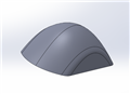
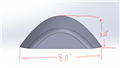
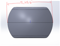
Hello everyone! I am having trouble trying to figure out how to align and dimension this part. I am programming offline to a supplied CAD model from the customer (I can't upload the file but I took screenshots of what the part looks like). The only dimensions they gave are the 3.000, 8.000, and 5.456" dimensions for the height, length, and width. The bottom of the part is flat and that will be my Z level and origin. As for the rest of the part I have no idea where to even start. Does anyone have any suggestions?
As far as dimensioning the part, I only need to report the 3 dimensions above and I was going to do profile of a surface on the rest of the part.
Thank you in advance!
I would rough-align z origin & level with 3 hits on granite (simulated datum), then go to one side of part like JacobCheverie said to take a 2 hit line. Use the two hit line to origin X and rotate Y about Z then i'd take a radius towards the bottom of the part on the big radius (parallel to z). Origin Y to the centroid of the radius for now.
Then to refine alignment: repeat 2point line on opposing side, create a midline of the two. repeat the radius on the opposing side of the part and create a midpoint between the two radii.
Level z to simulated bottom plane, Rotate to midline of sides, Origin Z to simulate bottom and X to the midline and Y to the midpoint of the 2 radii.
+1
Your first alignment doesn't have to be perfect. whenever you go for your second alignment just make sure you collect plenty of data. Also If you are struggling to capture the center of the top radius try using "fixed radius" instead of "Least_sqr" just for the location.
I would not use 2 point lines on the angle faces for a mid line as any difference in the angle of the two faces will change the centre line position best to do as Jacobcheverie stated and use planes on the angle faces then construct lines between the bottom face and the angles faces then a mid line. This way it does not matter what the angles are and if they change you will always end up with a true mid point line.
I would not use 2 point lines on the angle faces for a mid line as any difference in the angle of the two faces will change the centre line position best to do as Jacobcheverie stated and use planes on the angle faces then construct lines between the bottom face and the angles faces then a mid line. This way it does not matter what the angles are and if they change you will always end up with a true mid point line.