hexagon logo

Creating a dimension with MMB

Hi there,

I need help. I've received a ASME drawing in inches from a client (i usually work on ISO and with mm) and they've demanded that I measure a position with the MMC condition in the hole and for each datums (B and C).
The thing is that i don't know what values i have to put in the datum MMC size and why the third datum (C) appears like a plane in the repport when actually is a hole?

What i need to know is what values do i have to put in the datum MMC size and why the third datum have to be a plane for pc-dmis?
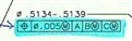
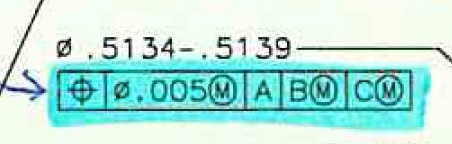

Attached is  the dimension requirement.

Thanks in advance.


Attached Files
Parents
  • To properly compute the MMB size of datum B, there should be a geometric tolerance (probably orientation) controlling datum feature B with respect to primary datum A (at RMB). You must add this dimension in PC-DMIS before the one in question. If there is no tolerance, PC-DMIS will effectively assume an orientation tolerance of 0 at MMC as this represents a mating situation and is the most conservative assumption.

    To properly compute the MMB size of datum C, there should be a geometric tolerance (probably position) controlling datum feature C with respect to primary datum A (at RMB) and secondary datum B (at MMB). You must add this dimension in PC-DMIS before the one in question. If there is no tolerance, PC-DMIS will effectively assume a position tolerance of 0 at MMC for the same reasons as above.

    All you have to enter for the limits of size are those that are seen on the blueprint for each datum feature. MMB size is a combination of feature size limits and geometric tolerances as described above.

    Since your tertiary datum is referenced at MMB, it must be a feature of size and thus cannot be a plane. There is nothing requiring the tertiary datum to be a plane in PC-DMIS software.
Reply
  • To properly compute the MMB size of datum B, there should be a geometric tolerance (probably orientation) controlling datum feature B with respect to primary datum A (at RMB). You must add this dimension in PC-DMIS before the one in question. If there is no tolerance, PC-DMIS will effectively assume an orientation tolerance of 0 at MMC as this represents a mating situation and is the most conservative assumption.

    To properly compute the MMB size of datum C, there should be a geometric tolerance (probably position) controlling datum feature C with respect to primary datum A (at RMB) and secondary datum B (at MMB). You must add this dimension in PC-DMIS before the one in question. If there is no tolerance, PC-DMIS will effectively assume a position tolerance of 0 at MMC for the same reasons as above.

    All you have to enter for the limits of size are those that are seen on the blueprint for each datum feature. MMB size is a combination of feature size limits and geometric tolerances as described above.

    Since your tertiary datum is referenced at MMB, it must be a feature of size and thus cannot be a plane. There is nothing requiring the tertiary datum to be a plane in PC-DMIS software.
Children
No Data