I had a doubt regarding the Size dimension option in PCDMIS.
While doing ISO dimensions - I found this option which is useful in giving desired output.
But I got strange feeling about how PCDMIS calculating dimensions.
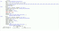
Since its a very small area , i had to use Vision system to create individual points and constructed as MAX.INSC circle.
Then i use " Size dimension " option to evaluate LP and GX together.
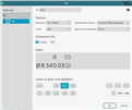
Dimension : Dia 8.54 + 0 (LP) , -0.03 ( GX )
Example : 1
Standard : ISO 14405-1
Here , 8.54 is nominal
LP is given to upper tol.
GX is given to lower tol.
So i got value as : UPPER SIZE - 8.549
LOWER SIZE - 8.528
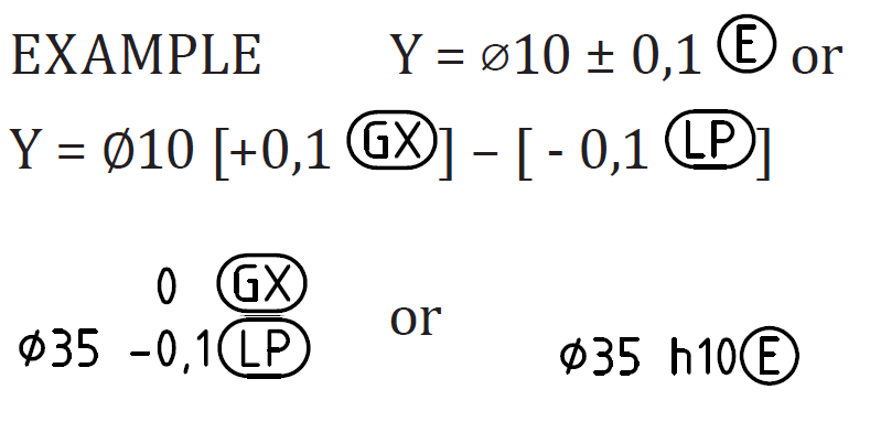
Example : 2
Standard : ISO 14405-1
8.54 is nominal
GX is given to upper tol.
LP is given to lower tol.
So i got value as : UPPER SIZE - 8.528
LOWER SIZE - 8.531
My question here is :
what is UPPER SIZE ?
How that is measured in software ?
Why I'm getting different LP , if I flip the modifiers ? ( 8.549 and 8.531 )
How LP value helps the functionality ?
Waiting for someone to clarify this......
Attached Files