Loaded CAD to verify nominals were correct, still no go. Recreating the FCF doesn't change anything either.
Program:
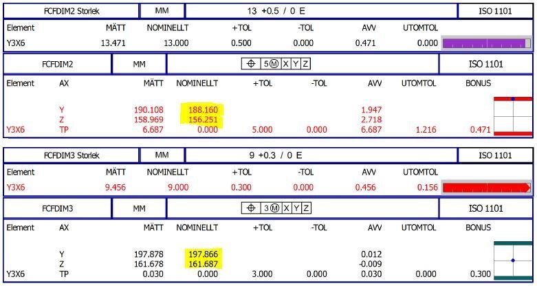
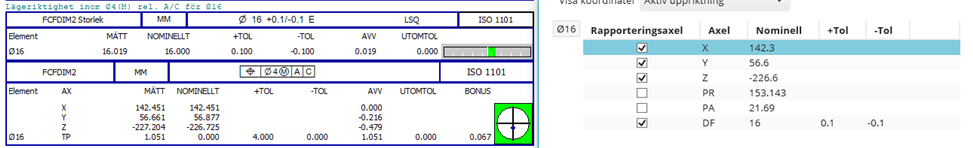
START =ALIGNMENT/START,RECALL:USE_PART_SETUP,LIST=YES
ALIGNMENT/END
MODE/MANUAL
CHECK/3,1
FORMAT/TEXT,OPTIONS,ID,HEADINGS,SYMBOLS, ;MEAS,NOM,TOL,DEV,OUTTOL, ,
LOADPROBE/3MM
TIP/TIP1, SHANKIJK=0, 0, 1, ANGLE=0
COMMENT/OPER,NO,FULL SCREEN=NO,AUTO-CONTINUE=NO,
Mät ytterdiameter på vänster rörände

OBS! Börja med tre stödpunkter!
Ø22 =FEAT/CONTACT/CIRCLE/DEFAULT,CARTESIAN,OUT,LEAST_SQR
THEO/<0,0,0>,<0,0,1>,22,0
ACTL/<627.234,644.389,262.38>,<0.2742149,0.1856828,0.94 3572>,21.968,0
TARG/<0,0,0>,<0,0,1>
START ANG=0,END ANG=360
ANGLE VEC=<1,0,0>
DIRECTION=CCW
SHOW FEATURE PARAMETERS=NO
SHOW CONTACT PARAMETERS=NO
PKT Ø22 =FEAT/POINT,CARTESIAN,NO
THEO/<0,0,0>,<0,0,1>
ACTL/<627.234,644.389,262.38>,<0.2742149,0.1856828,0.94 3572>
CONSTR/POINT,CAST,Ø22
DATDEF/B,FEATURES=Ø22,,
A1 =ALIGNMENT/START,RECALL:START,LIST=YES
ALIGNMENT/TRANS,XAXIS,PKT Ø22
ALIGNMENT/TRANS,YAXIS,PKT Ø22
ALIGNMENT/TRANS,ZAXIS,PKT Ø22
ALIGNMENT/END
COMMENT/OPER,NO,FULL SCREEN=NO,AUTO-CONTINUE=NO,
Mät spår i konsol

OBS! Börja med tre stödpunkter!
SPÅR =FEAT/CONTACT/ROUND SLOT/DEFAULT,CARTESIAN,IN
THEO/<295.6,-104.3,-147.2>,<-0.0605674,0.5000144,0.8638965>,<0.997564,0.0003141 ,0.069757>,9,11.8
ACTL/<-245.688,-241.238,-30.76>,<0.7142378,0.0169459,0.6996979>,<0.3198843, 0.8812814,-0.3478752>,9.169,13.982
TARG/<295.6,-104.3,-147.2>,<-0.0605674,0.5000144,0.8638965>,<0.997564,0.0003141 ,0.069757>
MEAS ANGLE=160
SHOW FEATURE PARAMETERS=NO
SHOW CONTACT PARAMETERS=NO
PKT Q =FEAT/POINT,CARTESIAN,YES
THEO/<295.6,-104.3,-147.2>,<-0.0605674,0.5000144,0.8638965>
ACTL/<-245.688,-241.238,-30.76>,<0.7142378,0.0169459,0.6996979>
CONSTR/POINT,CAST,SPÅR
A2 =ALIGNMENT/START,RECALL:A1,LIST=YES
ALIGNMENT/BF2D,ZPLUS,LEAST_SQR,CREATE WEIGHTS=NO,ROTANDTRANS,USE SCALING=NO,0,0,0,26.844
ITERATEANDREPIERCECAD=NO
Deviation Threshold=5,Pause Execution=NO
SHOWALLINPUTS=NO,SHOWALLPARAMS=NO
ALIGNMENT/END
WORKPLANE/YPLUS
A3 =ALIGNMENT/START,RECALL:A2,LIST=YES
ALIGNMENT/BF2D,YPLUS,LEAST_SQR,CREATE WEIGHTS=NO,ROTANDTRANS,USE SCALING=NO,0,0,0,21.172
ITERATEANDREPIERCECAD=NO
Deviation Threshold=5,Pause Execution=NO
SHOWALLINPUTS=NO,SHOWALLPARAMS=NO
ALIGNMENT/END
WORKPLANE/ZPLUS
COMMENT/OPER,NO,FULL SCREEN=NO,AUTO-CONTINUE=NO,
Mät ytterdiameter på höger rörände

OBS! Börja med tre stödpunkter!
HÖ RÖRÄNDE =FEAT/CONTACT/CIRCLE/DEFAULT,CARTESIAN,OUT,LEAST_SQR
THEO/<253,-142.5,-171.7>,<-0.2686794,-0.9630455,-0.0188342>,18,0
ACTL/<-285.276,-50.326,-175.445>,<-0.4032534,0.9128111,-0.0645188>,18.067,0
TARG/<253,-142.5,-171.7>,<-0.2686794,-0.9630455,-0.0188342>
START ANG=0,END ANG=360
ANGLE VEC=<-0.0699277,0,0.9975521>
DIRECTION=CCW
SHOW FEATURE PARAMETERS=NO
SHOW CONTACT PARAMETERS=NO
COMMENT/OPER,NO,FULL SCREEN=NO,AUTO-CONTINUE=NO,
Mät ytterdiameter på Ø16

OBS! Börja med tre stödpunkter!
Ø16 =FEAT/CONTACT/CIRCLE/DEFAULT,CARTESIAN,OUT,LEAST_SQR
THEO/<142.3,56.6,-226.6>,<0.4444073,0.8166771,-0.3681585>,16,0
ACTL/<-74.943,-141.655,-220.667>,<0.1179681,-0.9436953,-0.3090674>,16.024,0
TARG/<142.3,56.6,-226.6>,<0.4444073,0.8166771,-0.3681585>
START ANG=0,END ANG=360
ANGLE VEC=<-0.6379514,0,-0.7700766>
DIRECTION=CCW
SHOW FEATURE PARAMETERS=NO
SHOW CONTACT PARAMETERS=NO
WORKPLANE/ZPLUS
A4 =ALIGNMENT/START,RECALL:A3,LIST=YES
ALIGNMENT/BF3D,LEAST_SQR,CREATE WEIGHTS=NO,ROTANDTRANS,USE SCALING=NO,-1.755,3.229,-0.217,-141.985,175.886,-1.101
ITERATEANDREPIERCECAD=NO
Deviation Threshold=5,Pause Execution=NO
SHOWALLINPUTS=NO,SHOWALLPARAMS=NO
ALIGNMENT/END
REF A =FEAT/PLANE,CARTESIAN,TRIANGLE,NO
THEO/<0,0,0>,<0,0,1>
ACTL/<0,0,0>,<0,0,1>
CONSTR/PLANE,ALIGN,ZPLUS
DATDEF/A,FEATURES=REF A,,
REF C =FEAT/PLANE,CARTESIAN,TRIANGLE,NO
THEO/<0,0,0>,<0,1,0>
ACTL/<0,0,0>,<0,1,0>
CONSTR/PLANE,ALIGN,YPLUS
DATDEF/C,FEATURES=REF C,,
DIM DIM3= LOCATION OF CIRCLE Ø22 UNITS=MM ,$
GRAPH=OFF TEXT=OFF MULT=10.00 OUTPUT=NONE HALF ANGLE=NO
AX MEAS NOMINAL +TOL -TOL DEV OUTTOL
X 0.610 0.000 0.000 0.000 0.610 0.610 ->
Y 3.631 0.000 0.000 0.000 3.631 3.631 ->
Z 0.000 0.000 0.000 0.000 0.000 0.000 ->
END OF DIMENSION DIM3
DIM DIM2= LOCATION OF POINT PKT Q UNITS=MM ,$
GRAPH=OFF TEXT=OFF MULT=10.00 OUTPUT=NONE HALF ANGLE=NO
AX MEAS NOMINAL +TOL -TOL DEV OUTTOL
X 294.187 295.600 0.000 0.000 -1.413 -1.413 <-
Y -104.300 -104.300 0.000 0.000 0.000 0.000 ->
Z -147.200 -147.200 0.000 0.000 0.000 0.000 ->
END OF DIMENSION DIM2
COMMENT/REPT,
Mått 295.6 (±2)
DIM DIM4= LOCATION OF SLOT SPÅR UNITS=MM ,$
GRAPH=OFF TEXT=OFF MULT=10.00 OUTPUT=BOTH HALF ANGLE=NO
AX MEAS NOMINAL +TOL -TOL DEV OUTTOL
X 294.187 295.600 2.000 -2.000 -1.413 0.000 #-
END OF DIMENSION DIM4
COMMENT/REPT,
Lägeriktighet inom Ø2(M) rel. A/C för Ø22
FCFDIM1 =GEOMETRIC_TOLERANCE/STANDARD=ISO 1101,SHOWEXPANDED=NO,
SIZE/NOMINAL=22,TOLERANCE SPECIFICATION MODE=NOMINAL_WITH_DEVIATIONS,
UPPER TOLERANCE=0.15,LOWER TOLERANCE=-0.15,
SEGMENT_1,POSITION,DIAMETER,2,MMC,A,C,<dat>,
ADD
FEATURES/Ø22,,
COMMENT/REPT,
Lägeriktighet inom Ø4(M) rel. A/C för Ø16
FCFDIM2 =GEOMETRIC_TOLERANCE/STANDARD=ISO 1101,SHOWEXPANDED=NO,
SIZE/NOMINAL=16,TOLERANCE SPECIFICATION MODE=NOMINAL_WITH_DEVIATIONS,
UPPER TOLERANCE=0.1,LOWER TOLERANCE=-0.1,
SEGMENT_1,POSITION,DIAMETER,4,MMC,A,C,<dat>,
ADD
FEATURES/Ø16,,
COMMENT/REPT,
Lägeriktighet inom Ø4(M) rel. A/C för Ø18
FCFDIM3 =GEOMETRIC_TOLERANCE/STANDARD=ISO 1101,SHOWEXPANDED=NO,
SIZE/NOMINAL=18,TOLERANCE SPECIFICATION MODE=NOMINAL_WITH_DEVIATIONS,
UPPER TOLERANCE=0.1,LOWER TOLERANCE=-0.1,
SEGMENT_1,POSITION,DIAMETER,4,MMC,A,C,<dat>,
ADD
FEATURES/HÖ RÖRÄNDE,,
Ping neil.challinor
Rob Jensen