hexagon logo

Constraining the vector in Autofeature calculations

So far I have only seen that I can constrain the radius in feature calculations. Can we constrain result calculations to things like vector and position as well?

Right now we have a part with a free-form hourglass-like cavity on the inside. The drawing calls out that the circle formed by the smallest crosssection of this hourglass has a rather tight position tolerance. I figured I would just measure the hourglass like a cylinder and set the max inscribed fitting algorithm to obtain the smallest cross-section. Thing is, I would need to constrain the vector of this cylinder to exactly 1,0,0 IJK for the location to be correct.

Is this possible?
  • a tight position along the axis of the 'cylinder' or just the other 2 axis? hugely different question I'm thinking
  • I guess since it's not a true cylinder the question doesn't make a whole lot of GD&T sense. But the way we are going to interpret this callout is as a 2D true position of the circle formed by the smallest cross-section of the hourglass shape to the Y and Z axis. If they really wanted 3D axial position they should have called out a profile tolerance. You are correct, if I was trying to evaluate the whole surface for the position, a COMPLETELY different approach would have to be taken. This isn't even the silliest callout on this drawing.
  • My thoughts are construct a plane at the x location of the cylinder point with smallest radial value then pierce it with the cylinder axis and apply the y,z position tol to the pierce point. Obtaining that x location from cylinder points would be the fun part, feels like an array could get it but not sure exactly how if it can

    The real gurus will probably have better answers monday morning im curious what they say
  • I don't know of a way to force the vector of a cylinder to stay the same. Unfortunately, with an hour glass shape the cylinder will probably tilt one way or another when it is constructed.

    If you take many points at different levels (a bunch of vertical scans would probably be best) and construct a circle from those points, that will assume the vector is normal to the workplane. It would essentially be the same as a fixed vector cylinder. If you use the Max Inscribed fit method it should give you what you want. What is cool is then you can graph the circularity of that circle and you will see all the points in 3D space. The deviations will all point away from the max inscribed circle.
  • measure cylinder using autofeature (algorithm MAX_INSC)
    construct circle from cylinder. force theo of circle to be 0*1,0*1,1*1

    maybe that would work?
  • Not exactly, as far as I know, doesn't like constructing the circle.  There's a super-cumbersome way to do it, though (this also makes applicable datum features ASME correct).

    In this example, let's assume you want a female cylinder constrained perpendicular to a plane:  project each and every point in cylinder up to the plane.  Make a feature set.  Now make your max inscribed circle off that feature set. 

  • Let's assume you want a female cylinder constrained perpendicular to a plane:  project each and every point in cylinder up to the plane.  Make a feature set.  Now make your max inscribed circle off that feature set. 

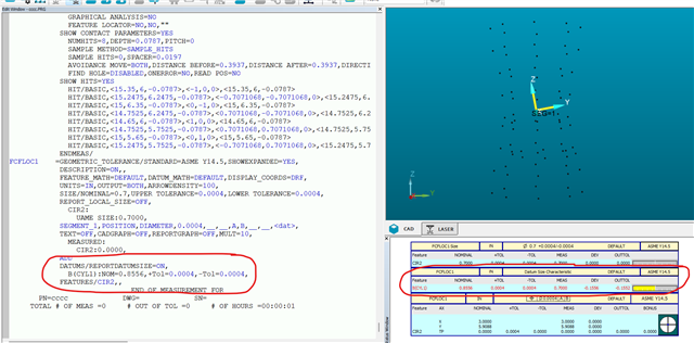
  • If you use the geometric tolerance command, you can make the plane the primary datum and the cylinder the secondary datum.  You can then report position of any other feature back to the primary datum plane and secondary datum cylinder and look at the datum sizes.

    This is a test I did with a dataset I created - hourglass shape that was Ø0.7 inches at it's smallest point.  My primary datum plane is inclined 10° about the X axis (this can be any angle) and you can see that the secondary datum size shows 0.7 inches - for this particular scenario, you ignore everything else since it is only the cylinder UAME size when it's orientation is constrained to to the plane that we are interested in.
    For ASME, datums are always constrained in both orientation and location.  For ISO, datums are constrained in orientation only.

  • Can't comment on latest version, but results were still slightly different in 2021 (test focused mostly on gross perpendicularity error), between canned PC-DMIS FCF method and what I described.  I'll continue micromanaging everything.