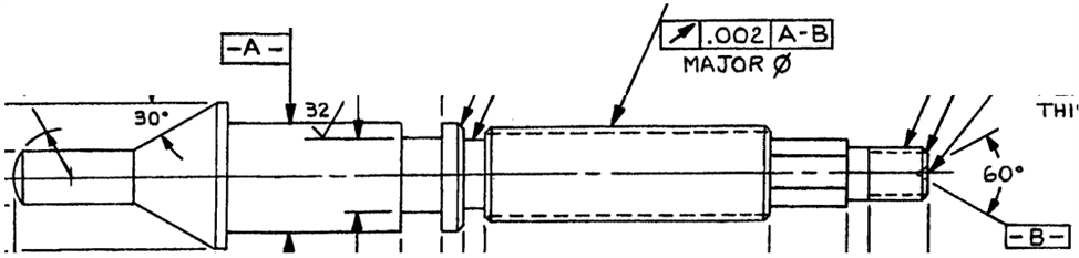
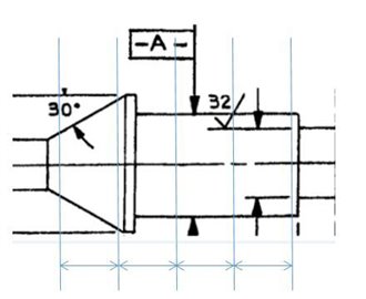
I have this rod that has a datum A cylinder and datum B is center drill. I can create the common datum for a runout tolerance but when I create the runout feature it won't let me because they're 2 different feature types. So I created a generic cylinder out of the cone then PC DMIS didn't like that one feature had surface data and the other one didn't. I then created a generic cylinder out of the measured cylinder and then it would let me make my runout FCF feature. Why can't I make the common datum out of 2 different features?
Because the features you are trying to use are not supported yet. Extract from the help
CommonDatums
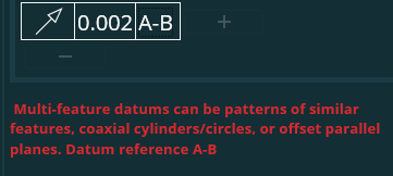
A common datum refers to a datum identifier like A-B or A-AB-B. It has one or more hyphens that separate defined datum identifiers. PC-DMIS supports two types of commondatums:
Coaxial cylindrical surface. These may have different nominal sizes and/or size tolerances. You may measure them as either cylinder features or circle features.
Offset parallel planes
The workaround would be to measure -A- as a cylinder and then construct a cast cylinder from it, measure -B- as a cone and again create a cast cylinder from it and then reference the cast cylinders as datum A & B. You will then be able to create a common datum A-B that satisfies the geometric tolerance commands' current common datum rules. We are working on expanding support for more types of common datum definitions for future versions.
1) Measure CYL_A
2) Measure CON_B
3) create generic points at..
-start of CYL_A
-end of CYL_A
-start of CON_B
-end of CON_B
4) Construct a 3d line (LIN_AB) through the 4 points
5) Create a new alignment (ALI_AB)..
-level through LIN_AB
-make LIN_AB origin
6) While recalling ALI_AB, report the runout of the feature you want evaluated against your current alignment
1) Measure CYL_A 2) Measure CON_B 3) create generic points at.. -start of CYL_A -end of CYL_A -start of CON_B -end of CON_B 4) Construct a 3d line (LIN_AB) through the 4 points 5) Create a new alignment (ALI_AB).. -level through LIN_AB -make LIN_AB origin 6) While recalling ALI_AB, report the runout of the feature you want evaluated against your current alignment
Be careful with end point of a cone, I would check if it's the vertex or not... If so, the line wouldn't represent the right axis, because of the total length of the cone in front of the measured length...
Maybe constructing pierce points between axes and generic planes would give right results ?
In addition, a datum on a cone should be a cone tangent on athe free side of material... And I believe PC-DMIS (nor any other soft ?) is unable to do it...
neil.challinor ?
JEFMAN , when using the geometric tolerance command with the math type set to default, we recalculate using constrained L2 (ASME) or constrained min/max (ISO). This applies to all features that have surface data, including cones, is that what you mean? We do deviate slightly from the standards in that we only allow a cone to constrain 4 degrees of freedom whereas the standards say that they should constrain 5. The fifth degree of freedom is supposed to be translation along the axis of the cone but the standards are not very clear on how this is supposed to be determined.
neil.challinor : nice !
Is there any way to construct the feature corresponding to the datum ?
I remember the time when the flatness was correctly calculated, but the associated feature was hidden somewhere in the soft
The only constructed datum features currently available are the constructed primary datum plane, constructed secondary datum line and constructed tertiary datum point. These were provided to enable users to simulate simple datum reference frames using a traditional alignment. We may consider making the constrained L2 / constrained min/max math options available for other constructions in the future - no set date yet though.
Hi everyone, I just thought I'd provide a sneak preview of what's coming in PC-DMIS 2023.1
We have significantly expanded support for different types of common datum. 2023.1 will support combinations up to five datum features or datum patterns and many more feature types as part of a common datum. This means that the case being discussed here (combination of a cone and a cylinder) will be supported. Please consider taking part in the 2023.1 technical preview when it goes live if you would like to learn more and try things out for yourself.