hexagon logo

Variation on Cylinder due to probe touching angle


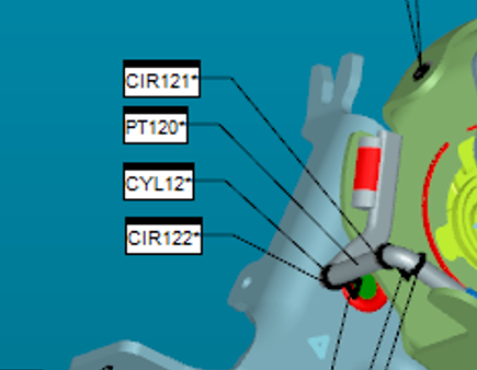
I learned from 101 that for cylinder, the probe should vertical touch the point ( we use analog probe with 2 mm header), the first 3 or 6 even 8 points compose a plane. I believe this definition is good for compensation of the probe header. Now we have a product with an around 5 mm diameter wire which welds on the part. On the drawing the wire could have 2 mm center variation on one workplane. The program measures it as a cylinder( touch 8 points in 180 degree) with a fix angle which I believe has 10 degree away from vertical cut the cylinder (around 80 degree to the plane). I wonder how much variation does this measurement bring it due to my concern and anything we could help reduce those kind of variation?

Thanks
Parents
  • if you want to exact the most accurate location & diameter of this wire:
    you should try to establish a true as-found type of axis of the wire (not depend on its theoretical location), by sampling a few hits with prudent prehit/retract distances (two circles for example),
    with the sample circles, you can establish an axis and locally within the routine align to it
    once locally aligned to the actual measured axis of the wire, you can then measure the circles with your hits normal to the wire.
    doing so would eliminate the potential cosine error, making the location and diameter most accurate.
Reply
  • if you want to exact the most accurate location & diameter of this wire:
    you should try to establish a true as-found type of axis of the wire (not depend on its theoretical location), by sampling a few hits with prudent prehit/retract distances (two circles for example),
    with the sample circles, you can establish an axis and locally within the routine align to it
    once locally aligned to the actual measured axis of the wire, you can then measure the circles with your hits normal to the wire.
    doing so would eliminate the potential cosine error, making the location and diameter most accurate.
Children